
Air conditioner system with draught fan waste heat recycling and control method of air conditioner system

An air-conditioning system and waste heat recovery technology, applied in heat recovery systems, air-conditioning systems, ventilation and heating energy recovery systems, etc., can solve the problems of complex structure, large energy loss, and non-energy saving, and achieve high control accuracy and dynamic response sensitive effect

Active Publication Date: 2020-02-11
JIANGXI QINGHUA TAIHAO SANBO ELECTRICAL MACHINE
View PDF21 Cites 1 Cited by
  • Summary
  • Abstract
  • Description
  • Claims
  • Application Information

AI Technical Summary

Problems solved by technology

[0002] The blower of the existing blower air-conditioning system is located at the air inlet of the air conditioner, which requires additional processing of the heat load of the blower, and the heating adopts electric heating or steam heating, and the control method is simple, the accuracy is not high, the energy loss is large, and the structure is complicated. energy saving

Method used


Image

  • Air conditioner system with draught fan waste heat recycling and control method of air conditioner system
  • Air conditioner system with draught fan waste heat recycling and control method of air conditioner system

Examples


Embodiment Construction

[0022] In order to make the purpose, technical solutions and advantages of the embodiments of the present invention clearer, the technical solutions in the embodiments of the present invention will be clearly and completely described below in conjunction with the drawings in the embodiments of the present invention. Obviously, the described embodiments It is a part of embodiments of the present invention, but not all embodiments. Based on the embodiments of the present invention, all other embodiments obtained by persons of ordinary skill in the art without creative efforts fall within the protection scope of the present invention.

[0023] The present invention will be described in further detail below in conjunction with the accompanying drawings.

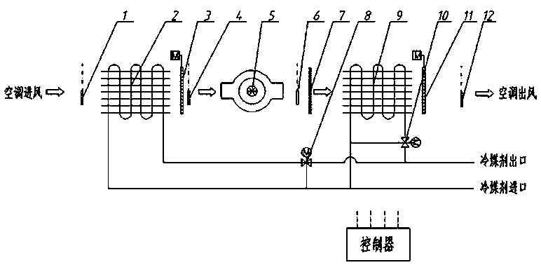
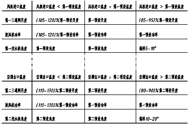
[0024] Such as Figure 1-2 As shown, an air conditioning system with fan waste heat recovery includes a first-stage heat exchanger 2, a first water retainer 3, a blower 5, an air filter 7, a second-stage heat exchanger 9, and a ...


PUM


Abstract

An air conditioner system with draught fan waste heat recycling comprises a first-level heat exchanger (2), a first water stop device (3), an air blower (5), an air filter (7), a second-level heat exchanger (9), a second water stop device (11) and a controller. The air conditioner system is characterized in that the first-level heat exchanger, the first water stop device, the air blower, the air filter, the second-level heat exchanger and the second water stop device are sequentially arranged in the airflow flow direction, an air conditioner air inlet temperature sensor is arranged at the upstream position of the first-level heat exchanger, and a draught fan inlet temperature sensor is arranged at the upstream position of the air blower and between the air blower and the first water stop device. Control precision is high, dynamic response is sensitive, more energy is saved, and the efficient and energy-saving type dehumidification air conditioner system accurate and controllable in temperature is achieved.

Description

technical field [0001] The invention relates to the field of air-conditioning systems, in particular to an air-conditioning system with fan waste heat recovery and a control method thereof, which is an accurate and controllable temperature, high-efficiency and energy-saving dehumidification air-conditioning system. Background technique [0002] The blower of the existing blower air-conditioning system is located at the air inlet of the air conditioner, which requires additional processing of the heat load of the blower, and the heating adopts electric heating or steam heating, and the control method is simple, the accuracy is not high, the energy loss is large, and the structure is complicated. energy saving. Contents of the invention [0003] The purpose of the present invention is to overcome the deficiencies in the prior art, provide an air conditioning system with fan waste heat recovery and its control method, and achieve control accuracy by setting and adjusting the ...

Claims


Application Information

Patent Timeline
IPC IPC(8): F24F3/00F24F12/00F24F13/30F24F13/28F24F13/22F24F11/89F24F11/46F24F11/64F24F11/84F24F11/77F24F11/74F24F110/10
CPCF24F3/00F24F12/00F24F13/22F24F13/28F24F13/30F24F11/46F24F11/64F24F11/74F24F11/77F24F11/84F24F11/89F24F2110/10Y02B30/56Y02B30/70
Inventor 万慧凯
Owner JIANGXI QINGHUA TAIHAO SANBO ELECTRICAL MACHINE
Learn More