
Fixture for impact test of grid stiffened plate

A technology of impact test and drop weight impact test, which is applied in the direction of impact test, mechanical component test, machine/structural component test, etc. It can solve the problem that the clamped test piece cannot meet the stability requirements, etc., and achieve improvement Consistency, the effect of improving test accuracy

Inactive Publication Date: 2020-02-11
HARBIN UNIV OF SCI & TECH
View PDF8 Cites 0 Cited by
  • Summary
  • Abstract
  • Description
  • Claims
  • Application Information

AI Technical Summary

Problems solved by technology

The drop weight impact test is an important test for the impact performance test of the grid-stiffened panels of composite materials. Due to the presence of grids in the grid-stiffened panels, the stability requirements cannot be met by clamping the specimens with the existing clamps, and cannot Precise impacts on different locations on the same specimen

Method used


Image

  • Fixture for impact test of grid stiffened plate
  • Fixture for impact test of grid stiffened plate
  • Fixture for impact test of grid stiffened plate

Examples


Embodiment Construction

[0022] The following will clearly and completely describe the technical solutions in the embodiments of the present invention with reference to the accompanying drawings in the embodiments of the present invention. Obviously, the described embodiments are only some, not all, embodiments of the present invention. Based on the embodiments of the present invention, all other embodiments obtained by persons of ordinary skill in the art without making creative efforts belong to the protection scope of the present invention.

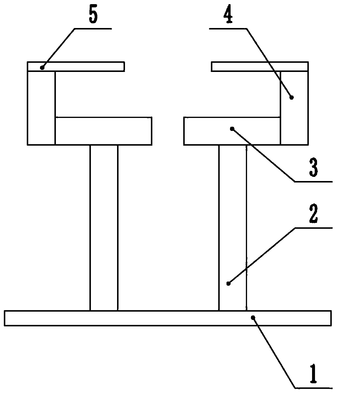
[0023] The purpose of the present invention is to provide a jig for the impact test of the grid stiffened plate, to solve the above-mentioned problems in the prior art, to ensure that the same position of different test pieces is impacted during the test, and to improve the test accuracy.

[0024] In order to make the above objects, features and advantages of the present invention more comprehensible, the present invention will be further described in detail be...


PUM


Abstract

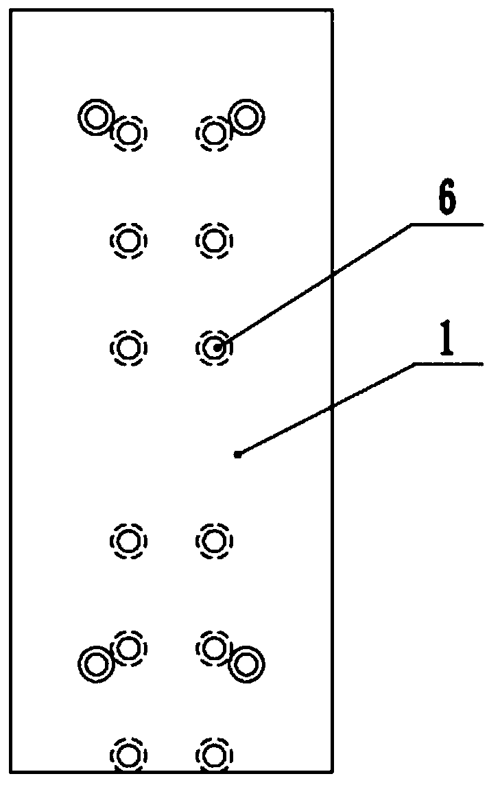
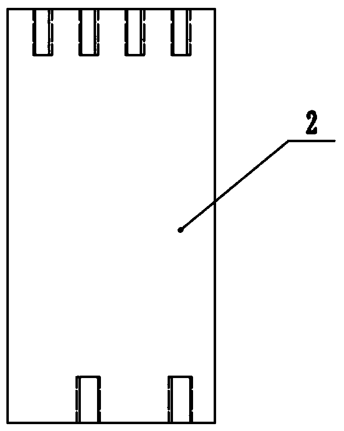
The invention discloses a fixture for an impact test of a grid stiffened plate. The fixture comprises a base, a support and a positioning platform, the base can be connected with a drop hammer impacttester, the support is detachably connected with the base, the installation positions of the support and the base can be adjusted, the positioning platform is arranged at the top of the support, and the positioning platform is provided with grooves which can fix ribs of a grid stiffened plate. During test, the grid stiffened plate is arranged on the positioning platform; ribs of the grating stiffened plate are located in grooves in the positioning platform, a covering abuts against the positioning platform, position where the base is connected with the support can be adjusted to adjust the hammer position of the drop hammer impact tester, and further impact requirements for different positions of the grid stiffened plate can be met. The grooves in the positioning platforms can fix the ribsof the grid stiffened plate, and the base is connected with the tester, so that impact positions of different test pieces can be kept the same when the test piece is replaced, and the impact positions of the different test pieces can be more consistent.

Description

technical field [0001] The invention relates to the technical field of clamping equipment, in particular to a clamp used for the impact test of a grid stiffened plate. Background technique [0002] A typical composite grid-reinforced structure is made of continuous fibers and organic composite materials, and has a structure consisting of a reinforced grid (grid) and a supported shell (skin). The drop weight impact test is an important test for the impact performance test of the grid-stiffened panels of composite materials. Due to the presence of grids in the grid-stiffened panels, the stability requirements cannot be met by clamping the specimens with the existing clamps, and cannot Precise impacts to different locations on the same specimen. [0003] Therefore, how to provide a jig for the impact test of the composite grid-stiffened plate, to ensure that the same position of different test pieces is impacted during the test, and to improve the test accuracy has become an u...

Claims


Application Information

Patent Timeline
Patent Type & Authority Applications(China)
IPC IPC(8): G01N3/04G01M7/08G01M13/00
CPCG01M7/08G01M13/00G01N3/04
Inventor 严实徐林贾佳乐
Owner HARBIN UNIV OF SCI & TECH
Learn More