Detachable paint brush production technology

A production process and technology of paint brushes, applied in the field of paint brushes, can solve the problems of non-environmental protection, energy saving, waste of handles, etc.

Active Publication Date: 2020-02-14
无锡品知信息科技有限公司
View PDF4 Cites 0 Cited by
  • Summary
  • Abstract
  • Description
  • Claims
  • Application Information

AI Technical Summary

Problems solved by technology

[0005] The purpose of the present invention is to address the shortcomings of the prior art, by setting the positioning step of the clamping part, instead of directly installing the bristle part and the handle part in a traditional way, using the clamping part as an intermediary, the bristle part is clamped a

Method used


Image

  • Detachable paint brush production technology
  • Detachable paint brush production technology
  • Detachable paint brush production technology

Examples


Embodiment 1

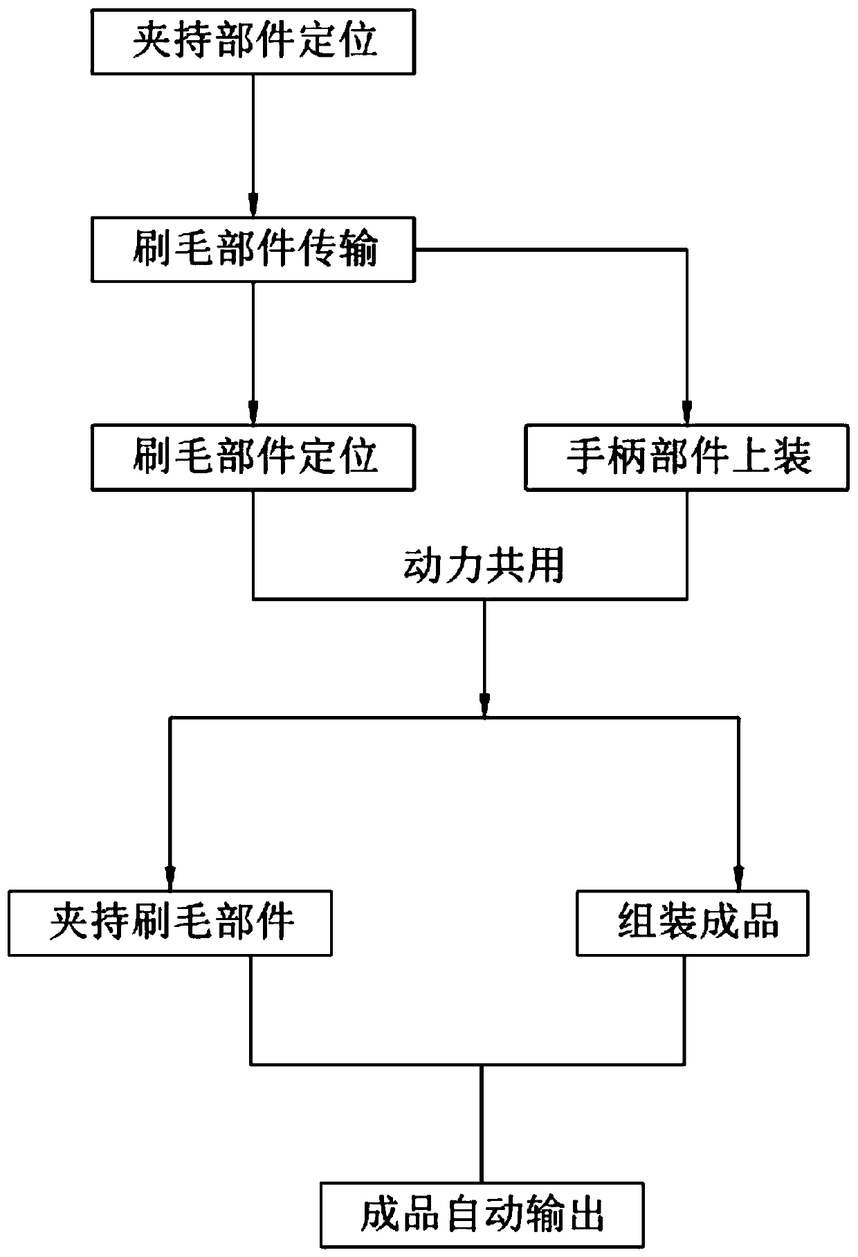
[0093] Such as Figure 16 Shown, a kind of detachable paint brush production process comprises:

[0094] Step 1, positioning the clamping component, manually placing the clamping component 32 on the mounting column 312 of the support assembly 31, and using the mounting column 312 to achieve positioning;

[0095] Step 2, bristle component transmission, one end of the bristle component 13 is located on the first transmission assembly 11 and the other end is suspended outside the first transmission assembly 11, until it is transmitted to the second transmission assembly 12, and suspended outside the first transmission assembly 11 The bristle part 13 is transported on the second transport assembly 12;

[0096] Step 3, position the bristle part, start the extrusion assembly 33, the insertion rod 334 of the extrusion assembly 33 presses down on the lower clamping plate 3221 of the lower clamping part 32 through the socket 335, and the bristle part 13 is transported to the clamping ...

Embodiment 2

[0112] Referring to Embodiment 1, an automatic output device for paint brushes of the present invention is described.

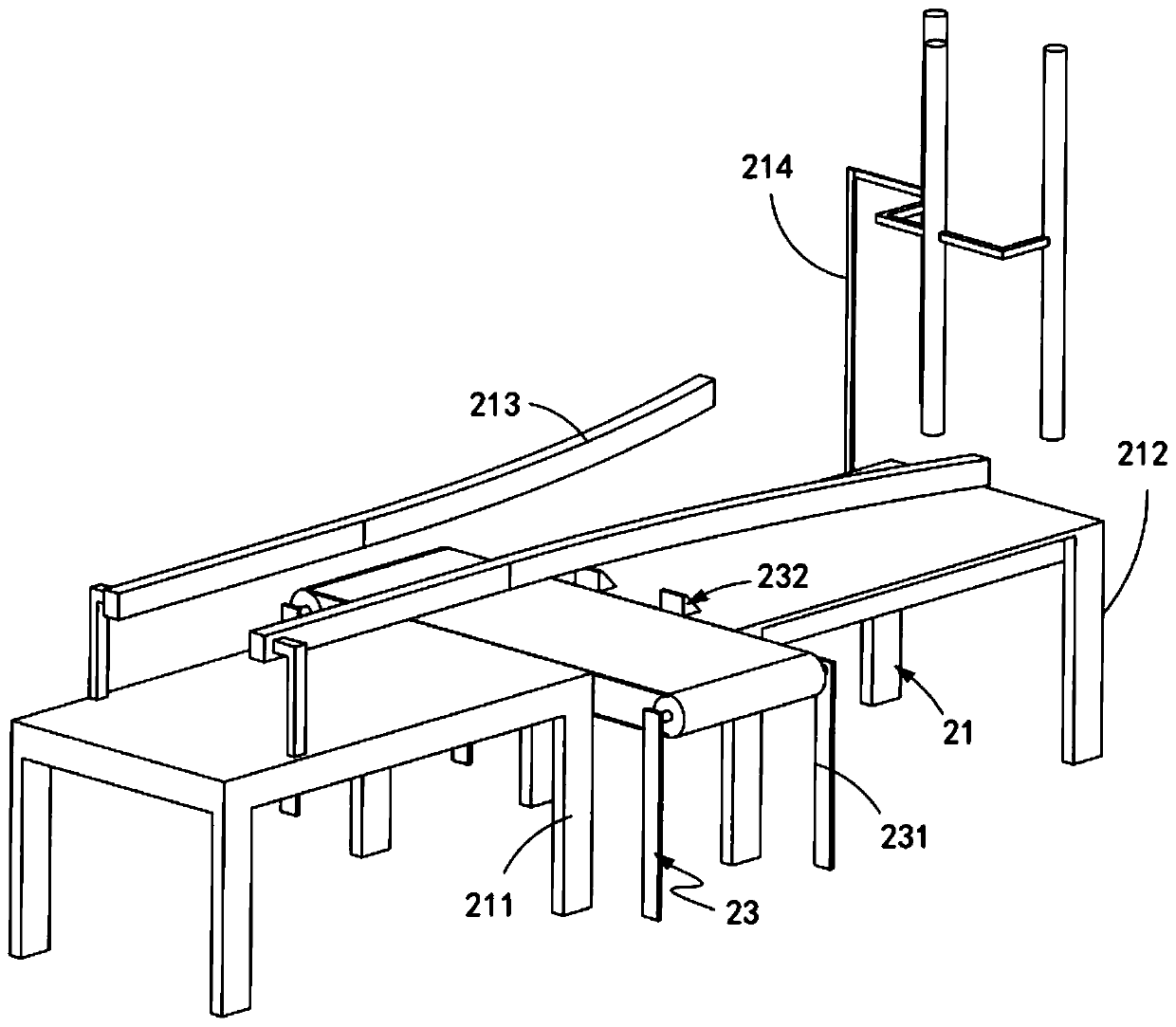
[0113] Such as figure 1 Shown, a kind of automatic output device for paintbrush, comprises:

[0114] The bristle feeding device 1, the bristle feeding device 1 includes a first transmission assembly 11 and a second transmission assembly 12 arranged on one side of the first transmission assembly 11, one end of the bristle component 13 is located on the first transmission assembly 11 And the other end is located on the second transmission component 12;

[0115] Handle feeding device 2, said handle feeding device 2 includes a third conveying assembly 21 arranged perpendicularly to the conveying direction of said first conveying assembly 11, and a flat pushing assembly arranged slidably along said conveying direction of said third conveying assembly 21 22 and the feeding assembly 23 arranged vertically with the third conveying assembly 21 and arranged along the...

Embodiment 3

[0169] Such as Figure 15 As shown, the parts that are the same as or corresponding to those in the second embodiment are marked with the corresponding reference numerals in the second embodiment. For the sake of simplicity, only the differences from the first embodiment will be described below. The difference between this embodiment three and embodiment one is:

[0170] further, such as Figure 15 As shown, the transmission assembly 34 includes:

[0171] A transmission rod a341, the transmission rod a341 is fixedly connected to the driving rod 333 and arranged vertically thereto;

[0172] Switching member 342, said switching member 342 includes a rack a3421 fixedly connected with said transmission rod a341 and arranged vertically, a frame e3422 installed on the frame d331, a rotating shaft c3423 rotatably arranged on said frame e3422 , the gear a3424 meshed with the rack a3421 and fixedly arranged with the rotating shaft c3423, the gear b3425 arranged on one side of the ge...


PUM

PropertyMeasurementUnit
Lengthaaaaaaaaaa

Abstract

The invention relates to a detachable paint brush production technology. The technology comprises the steps of step 1, positioning a clamping component: manually placing the clamping component on an installation column of a support component, and achieving positioning by using the installation column; step 2, transmitting a bristle component, positioning one end of the bristle component on a firsttransmission component, while enabling the other end to be suspended on the outer side of the first transmission component until the bristle component is transmitted to a second transmission component, namely that the bristle component suspended on the outer side of the first transmission component is transmitted to the second transmission component; step 3, positioning the bristle component; step 4, assembling a handle component, being synchronous with the step 3; step 5, clamping the bristle component; step 6, assembling into a finished product, being synchronous with the step 5; and step 7, automatically outputting the finished product. According to the detachable paint brush production technology, the technical problems that if the hairbrush of the paint brush is damaged, the paint brush needs to be wholly replaced with the new paint brush, and thus the handle is wasted, and the handle is made on wood, so as not to be environmentally friendly and not saving in energy are solved.

Description

technical field [0001] The invention relates to the technical field of paint brushes, in particular to a production process of a detachable paint brush. Background technique [0002] Paint tools are products used when painting paint. Some are used for pre-painting treatment and some are used for painting. They mainly include pig hair brushes, wool brushes, rollers, and putty knives. Paint tools are mainly divided into functions according to their functions. : Filling, scraping, grinding, dressing, brushing, spraying, cleaning, etc., and the paint tray is one of the paint holding tools, which is mainly used to hold the paint so that the workers can dip the paint. [0003] The patent document with the patent number CN2018209275982 discloses a portable multi-functional paint tray. Two paint scraping boards are arranged symmetrically on both sides of the inner wall of the tray, and a pedal and a paint brush storage box are arranged on one side of the front end of the tray body. ...

Claims


Application Information

Patent Timeline
IPC IPC(8): A46D3/04A46D3/08
CPCA46B2200/202A46D3/04A46D3/082A46D3/085A46D3/087
Inventor 开宗兴
Owner 无锡品知信息科技有限公司
Why Eureka
Try Eureka