Micro-fluidic base plate, and micro-fluidic structure and driving method thereof
A microfluidic, substrate technology, applied in the field of microfluidics, can solve the problem of low droplet control accuracy
- Summary
- Abstract
- Description
- Claims
- Application Information
AI Technical Summary
Problems solved by technology
Method used
Image

Examples
Embodiment 1
[0065] This embodiment provides a microfluidic substrate, including a substrate, on which a plurality of driving electrodes for driving liquid droplet movement are arranged, each driving electrode is arranged on the same layer and there is a space between adjacent driving electrodes; the microfluidic substrate is also include:
[0066] At least one auxiliary electrode for driving the movement of the droplet is arranged on the substrate, the auxiliary electrode is at least partly arranged in the interval, and is arranged in a different layer from the driving electrode.
[0067] In the microfluidic substrate of this embodiment, an auxiliary electrode that can be used to drive the movement of the droplet is provided at the interval between the driving electrodes. The driving electric field is also formed at the gap between the electrodes, eliminating or reducing the position where the driving electric field cannot be formed, and achieving smoother control of the droplet.
Embodiment 2
[0069] Such as Figure 2 to Figure 13 As shown, the present embodiment provides a microfluidic substrate, which includes:
[0070] base 8;
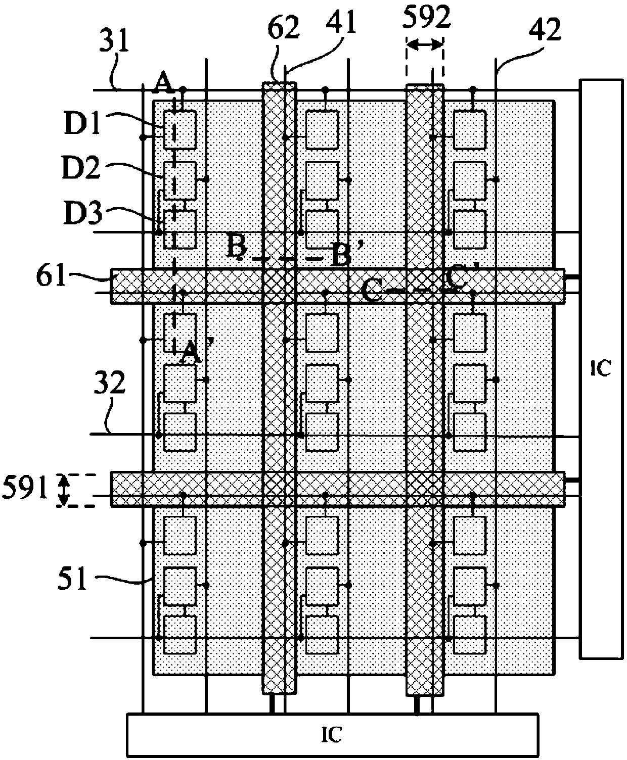
[0071] A plurality of driving electrodes 51 used to drive the movement of the droplet 9 on the substrate 8, each driving electrode 51 is arranged on the same layer and has a gap 59 between adjacent driving electrodes 51;
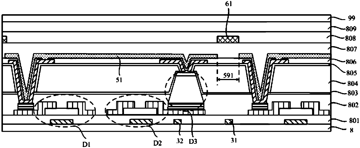
[0072] At least one auxiliary electrode 6 for driving the movement of the droplet 9 is provided on the substrate 8. The auxiliary electrode 6 is at least partially arranged in the gap 59 and is arranged in a different layer from the driving electrode 51.
[0073] Wherein, the base 8 refers to a substrate for carrying other structures, which may be in the shape of a plate. And a plurality of driving electrodes 51 are arranged on the same layer, and are arranged in an array for applying a driving voltage to drive the movement of the droplet 9; obviously, since the driving electrodes 51 are arranged on the same layer, th...
Embodiment 3
[0142] Such as Figure 2 to Figure 13 As shown, the present embodiment provides a microfluidic structure, which includes:
[0143] The aforementioned microfluidic substrate;
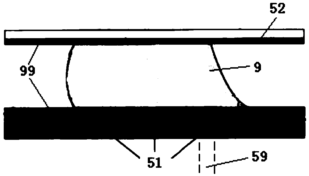
[0144] The box substrate opposite to the microfluidic substrate, the side of the microfluidic substrate with the drive electrodes 51 faces the box substrate, and the side of the box substrate facing the microfluidic substrate is provided with a common electrode 52 opposite to each drive electrode 51 , a space for accommodating the droplet 9 is formed between the microfluidic substrate and the box substrate.
[0145] That is to say, the above microfluidic substrate can be arranged opposite to the box substrate to form a microfluidic structure, wherein the common electrode 52 is set in the box substrate, so that the required driving electric field can be formed between the two substrates to drive The droplet 9 located between the two substrates moves.
[0146] Preferably, the microfluidic substrate is p...
PUM
 Abstract
Description
Claims
Application Information
 - R&D
- Intellectual Property
- Life Sciences
- Materials
- Tech Scout
- Unparalleled Data Quality
- Higher Quality Content
- 60% Fewer Hallucinations
Browse by: Latest US Patents, China's latest patents, Technical Efficacy Thesaurus, Application Domain, Technology Topic, Popular Technical Reports.
© 2025 PatSnap. All rights reserved.Legal|Privacy policy|Modern Slavery Act Transparency Statement|Sitemap|About US| Contact US: help@patsnap.com