
A microfluidic sampling system

A sampling system and microfluidic technology, applied in the field of microfluidics, can solve the problems of liquid residue, complex structure, affecting sampling accuracy, etc.

Active Publication Date: 2021-05-04
NANJING UNIV OF SCI & TECH
View PDF10 Cites 0 Cited by
  • Summary
  • Abstract
  • Description
  • Claims
  • Application Information

AI Technical Summary

Problems solved by technology

For example Jessica Melin&Stephen R.Quake, Microfluidic Large-ScaleIntegration: The Evolution of Design Rules for Biological Automation (J), Annu.Rev.Biomol.Struct.2007.36:213-231. The method of controlling the opening and closing of the control channel to complete the quantitative sampling of micro samples. In order to realize online quantitative sampling, this method usually requires multiple control microvalves, the structure is relatively complicated, and the flow dead zone in the microvalve is likely to cause liquid residue, which affects the sampling accuracy.

Method used


Image

  • A microfluidic sampling system
  • A microfluidic sampling system
  • A microfluidic sampling system

Examples


Embodiment Construction

[0019] The present invention will be further introduced below in conjunction with the accompanying drawings and specific embodiments.

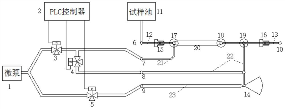
[0020] combine figure 1 , a microfluidic sampling system of the present invention, comprising a pneumatic drive and control module, a quantitative sampling module, and a negative pressure generator 14; the quantitative sampling module includes a sample pool 11, an inlet working channel 12, a first one-way Valve 15, first steam trap 17, quantitative sampling chamber 20, second steam trap 18, third steam trap 19, second one-way valve 16, outlet working channel 13;

[0021] The sample pool 11 is connected to the inlet end of the quantitative sampling chamber 20 through the inlet working channel 12, and the first check valve 15 is arranged on the working channel 12; the outlet end of the quantitative sampling chamber 20 passes through the outlet working channel 13 Connected to the sample outlet 10, the outlet working channel 13 is provided with a...


PUM


Abstract

The invention discloses a microfluidic sampling system, which includes a quantitative sampling module, an air pressure drive and control module, and a negative pressure generator; the quantitative sampling module includes a sample pool, an inlet working channel, a first one-way valve, a first hydrophobic Valve, quantitative sampling chamber, second steam trap, third steam trap, second one-way valve, inlet working channel; the first one-way valve is set on the inlet working channel; the second one-way valve is set on the outlet working channel The inlet and outlet ports of the quantitative sampling chamber are respectively the first steam trap and the second steam trap; a third steam trap is arranged between the second steam trap and the second one-way valve; the pneumatic drive and control module includes a micro air pump, The miniature solenoid valve and the controller, the air pump is the air source to provide the driving pressure, the solenoid valve and the controller form the control unit to control the on-off of the driving pressure. The system can improve the precision of quantitative sample injection, and can control the flow rate and flow rate of the sample according to the principle of pulse modulation during sample injection, and can save the cost of sample injection.

Description

technical field [0001] The invention belongs to the field of microfluidic technology, in particular to a microfluidic sampling system. Background technique [0002] Microfluidics is an interdisciplinary science and technology involving fluid mechanics, precision machinery, biomedicine, chemistry, etc. It is widely used in biochemical analysis, medical diagnosis, drug screening, etc. Due to the advantages of fewer samples / reagents and convenient miniaturization of instruments and equipment, it has achieved rapid development in recent years. Fluid sampling is a key link in the engineering application of microfluidic technology, involving quantitative sampling, fluid drive and sampling flow rate control, etc. This operation can be accomplished with a built-in integrated micropump, but the structure is complex and costly, and it is not suitable for disposable microfluidic chips. If the sample feeding methods such as external syringe pump and pressure pump are used, it is easil...

Claims


Application Information

Patent Timeline
Patent Type & Authority Patents(China)
IPC IPC(8): B01L3/00
CPCB01L3/5027
Inventor 段钰彤夏焕明
Owner NANJING UNIV OF SCI & TECH
Learn More