
A mold for manufacturing and processing motor rotor sheet

A technology for processing molds and motor rotors. It is used in manufacturing tools, forming tools, metal processing equipment, etc. It can solve the problems of scrap punching, affecting the service life of molds, and large differences in stamping dimensions, so as to improve work efficiency and reduce disassembly time. , the effect of reducing friction

Active Publication Date: 2021-06-08
温岭市开天机电有限公司
View PDF11 Cites 0 Cited by
  • Summary
  • Abstract
  • Description
  • Claims
  • Application Information

AI Technical Summary

Problems solved by technology

[0004] (1) When the traditional stamping die stamps the silicon steel sheet, when the progressive die is used, it is necessary to complete two or more stamping processes at different stations in one stroke of the press. It is easy to cause the punching position to shift during the stamping process, resulting in a large difference between the punching size and the standard part, resulting in the punching being a waste product
[0005] (2) When the traditional punching die stamps the silicon steel sheet, when the composite die is used, two or more stamping processes need to be completed at the same station at the same time in one stroke of the press, resulting in the die It is easy to be subjected to a large impact force, which affects the service life of the mold, and the punched workpiece is easy to get stuck in the processing position of the mold

Method used


Image

  • A mold for manufacturing and processing motor rotor sheet
  • A mold for manufacturing and processing motor rotor sheet
  • A mold for manufacturing and processing motor rotor sheet

Examples


Embodiment Construction

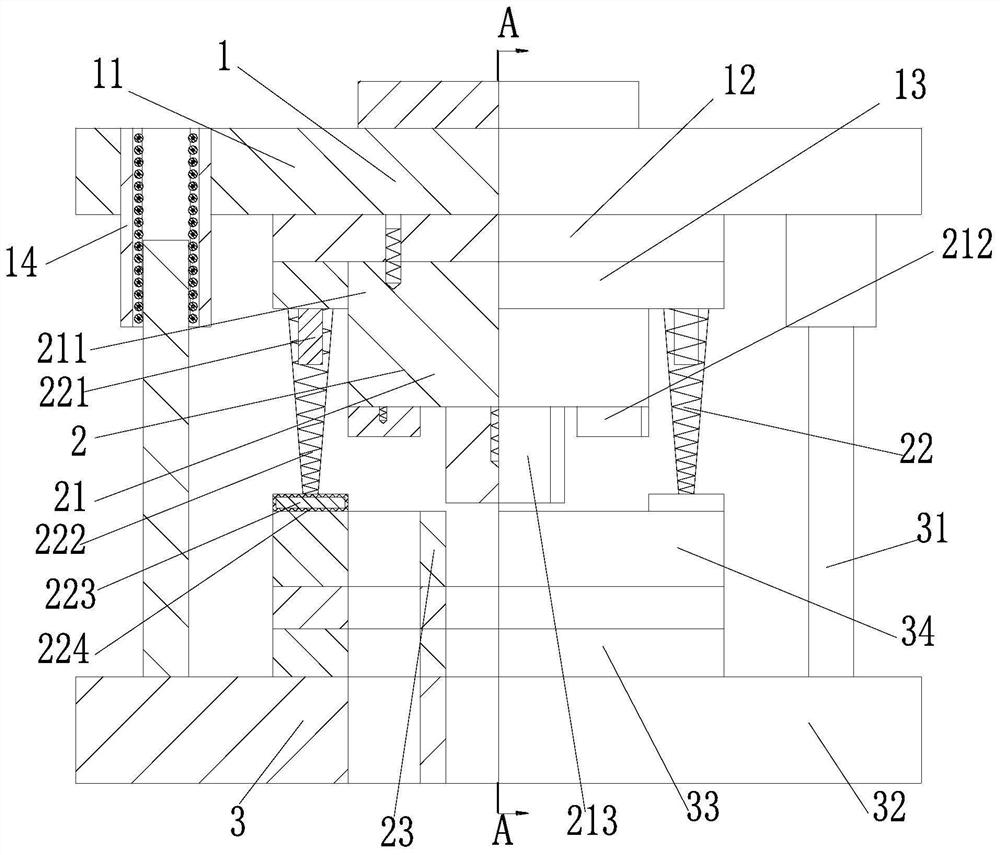
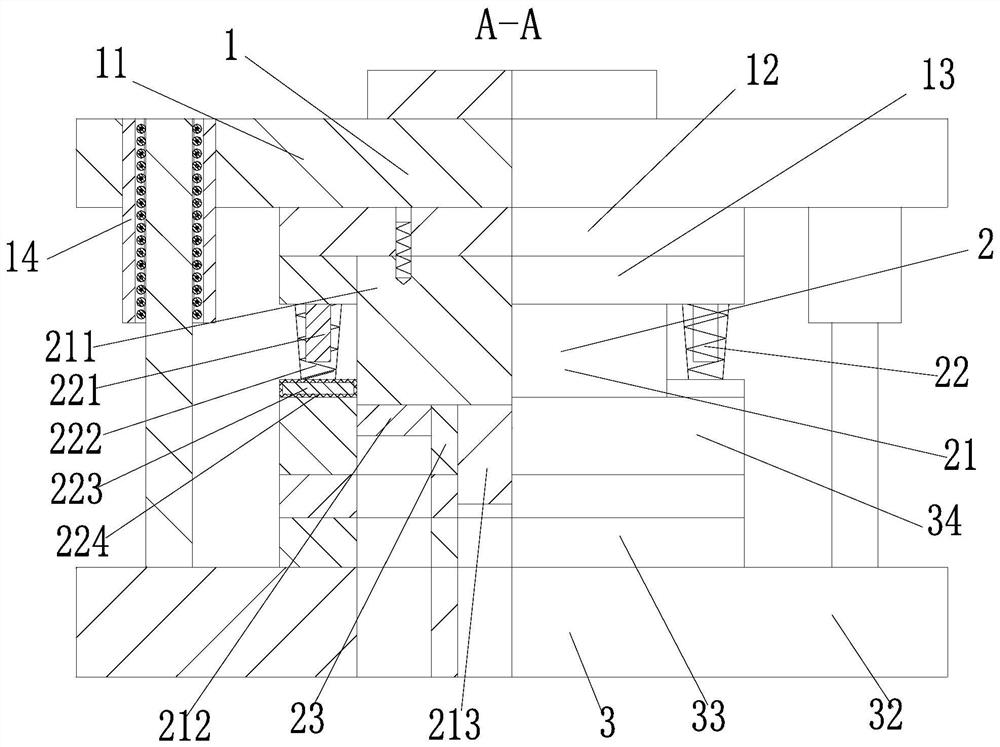
[0031] In order to make the technical means realized by the present invention, creative features, goals and effects easy to understand, the following combination Figure 1 to Figure 6 , to further elaborate the present invention.

[0032] A kind of mold for manufacturing and processing motor rotor sheet, comprising an upper die device 1, a processing device 2 and a lower die device 3, a processing device 2 is installed at the lower end of the upper die device 1, and a lower die device 3 is installed at the lower end of the processing device 2; :

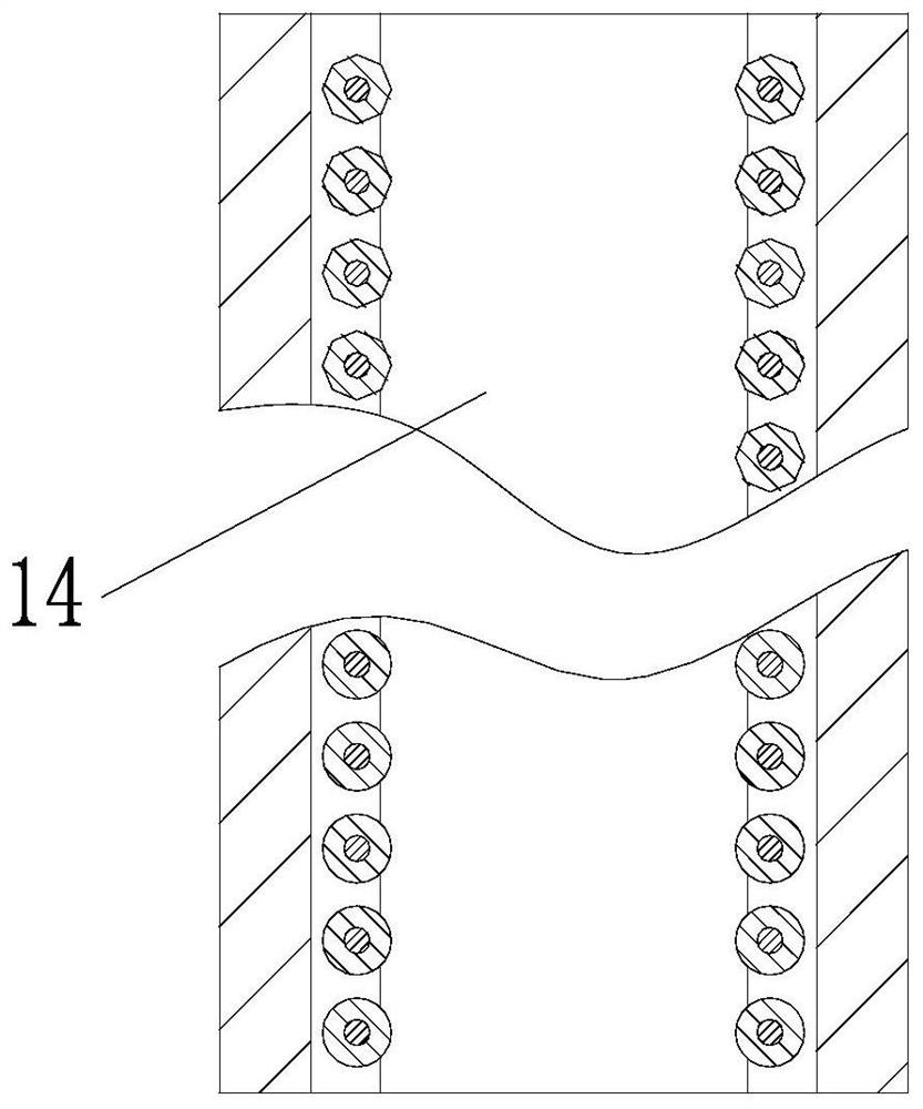
[0033] The upper mold device 1 includes an upper mold base 11, an upper template 12, a punch fixing plate 13 and a guide sleeve 14, the lower end of the upper mold base 11 is equipped with an upper template 12 through screws, and the lower end of the upper mold base 12 is fixed with a punch through screws. The plate 13, the left and right sides of the upper mold base 11 are evenly and symmetrically provided with circular grooves, an...


PUM


Abstract

The invention relates to a mold for manufacturing and processing motor rotor slices, including an upper die device, a processing device and a lower die device, a processing device is installed at the lower end of the upper die device, and a lower die device is installed at the lower end of the processing device. Matching with the lower mold through the guide post and the guide sleeve, the trajectory of the processing device is restricted. When the punch moves downward, the spring frame fixes the silicon steel sheet. Finally, the punch and the die cooperate to punch out the punching sheet, and the spring Due to the extrusion force, the frame produces a reaction force. When the punch moves upward, the spring frame generates a downward extrusion force on the edge of the punch, so that the punch stuck on the punch falls, and the hole shaft is used to The protruding height of the lower end is greater than the height of the rotor block, so that every time the silicon steel sheet is punched, the rotor slot and blanking, the hole shaft and the rotor block are used to fix and guide the silicon steel sheet.

Description

technical field [0001] The invention relates to the technical field of mold processing for motor manufacturing, in particular to a mold for manufacturing and processing motor rotor punching pieces. Background technique [0002] Motor rotor punching is a kind of workpiece that is stamped from 0.3mm silicon steel sheet and becomes a punching sheet of different specifications to be suitable for the use of motor stator rotors with different powers. Due to the wide use of motors, the demand for motor rotor punching continues to increase. The quality requirements of the film are also getting higher and higher. [0003] In the stamping process, due to the structural limitations of the stamping sheet, there are the following problems in the actual operation process: [0004] (1) When the traditional stamping die stamps the silicon steel sheet, when the progressive die is used, it is necessary to complete two or more stamping processes at different stations in one stroke of the pres...

Claims


Application Information

Patent Timeline
Patent Type & Authority Patents(China)
IPC IPC(8): B21D37/08B21D37/12B21D35/00B21D28/04B21D45/04H02K15/02
CPCB21D28/04B21D35/001B21D35/002B21D37/08B21D37/12B21D45/04H02K15/024
Inventor 黄三妹邹帅虎
Owner 温岭市开天机电有限公司
Learn More