
Automatic welding and stamping integrated equipment for point contact type silver contact

A technology of automatic welding and silver contacts, applied in other manufacturing equipment/tools, manufacturing tools, etc., can solve the problems of high labor intensity, difficult to grasp the position to be welded, high production cost, etc., and achieve the effect of increasing the feeding speed

Active Publication Date: 2020-02-14
WENZHOU JUXING ELECTRIC CONTACT TECH
View PDF6 Cites 9 Cited by
  • Summary
  • Abstract
  • Description
  • Claims
  • Application Information

AI Technical Summary

Problems solved by technology

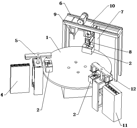
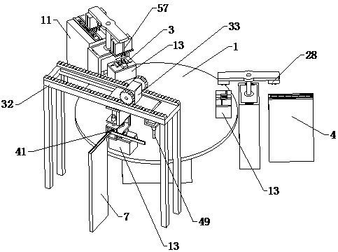
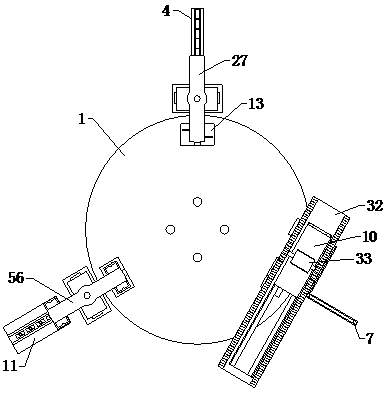
[0002] Contact welding is a very critical process for the electrical industry. Silver contacts are the key components for turning on and off the current. At present, many small and medium-sized machining enterprises are manually welding silver contacts. For loading and unloading, the contacts need to be positioned while welding, which is generally done manually. Manual positioning is not easy to grasp the position to be welded, and it is easy to produce offsets. Manual loading and unloading work is inefficient. Production The cost is high and the labor intensity is high. Therefore, we propose an automatic welding and stamping integrated equipment for point-contact silver contacts in order to solve the above-mentioned problems.

Method used


Image

  • Automatic welding and stamping integrated equipment for point contact type silver contact
  • Automatic welding and stamping integrated equipment for point contact type silver contact
  • Automatic welding and stamping integrated equipment for point contact type silver contact

Examples


Embodiment Construction

[0026] The technical solutions of the present invention will be further described below in conjunction with the accompanying drawings and through specific implementation methods.

[0027] Wherein, the accompanying drawings are only for illustrative purposes, showing only schematic diagrams, rather than physical drawings, and should not be construed as limitations on this patent; in order to better illustrate the embodiments of the present invention, some parts of the accompanying drawings will be omitted, Enlargement or reduction does not represent the size of the actual product; for those skilled in the art, it is understandable that certain known structures and their descriptions in the drawings may be omitted.

[0028] In the drawings of the embodiments of the present invention, the same or similar symbols correspond to the same or similar components; , "inner", "outer" and other indicated orientations or positional relationships are based on the orientations or positional ...


PUM


Abstract

The invention relates to the technical field of silver contact machining, in particular to automatic welding and stamping integrated equipment for a point contact type silver contact. The automatic welding and stamping integrated equipment comprises a rotary disc and further comprises a contact piece feeding mechanism, a silver contact feeding and welding mechanism and a discharging mechanism. Three clamping assemblies evenly distributed around the circumference of the rotary disc are arranged on a table top of the rotary disc. Each clamping assembly is provided with a material bearing jig capable of containing a workpiece. The contact piece feeding mechanism, the silver contact feeding and welding mechanism and the discharging mechanism are located on one sides of the clamping assembliescorrespondingly. The contact piece feeding mechanism comprises a contact piece feeding rail and a contact piece feeding assembly. The silver contact feeding and welding mechanism comprises a horizontal reversing assembly, a silver contact feeding rail, a guiding-in assembly and a welding and stamping assembly. The horizontal reversing assembly is provided with a movable plate. The discharging assembly comprises a discharging rail and a material moving assembly. By means of the equipment, automatic feeding and discharging can be achieved, a contact piece is automatically positioned, the silvercontact can be welded while stamping is conducted, and the production efficiency is improved.

Description

technical field [0001] The invention relates to the technical field of silver contact processing, in particular to an automatic welding and stamping integrated equipment for point contact silver contacts. Background technique [0002] Contact welding is a very critical process for the electrical industry. Silver contacts are the key components for turning on and off the current. At present, many small and medium-sized machining enterprises are manually welding silver contacts. For loading and unloading, the contacts need to be positioned while welding, which is generally done manually. Manual positioning is not easy to grasp the position to be welded, and it is easy to produce offsets. Manual loading and unloading work is inefficient. Production The cost is high and the labor intensity is high. Therefore, we propose an automatic welding and stamping integrated equipment for point-contact silver contacts in order to solve the above-mentioned problems. Contents of the invent...

Claims


Application Information

Patent Timeline
Patent Type & Authority Applications(China)
IPC IPC(8): B23P23/00
CPCB23P23/00
Inventor 黄光临黄进卯王垂浪
Owner WENZHOU JUXING ELECTRIC CONTACT TECH
Learn More