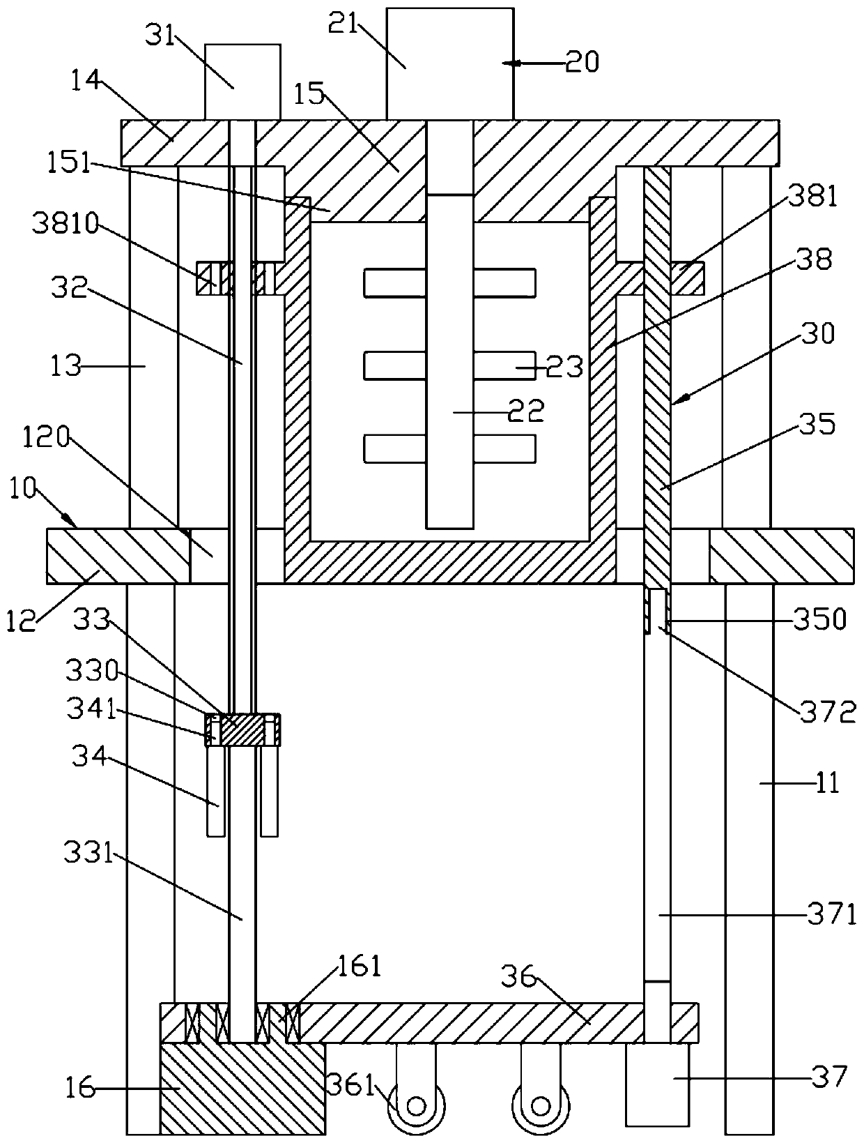
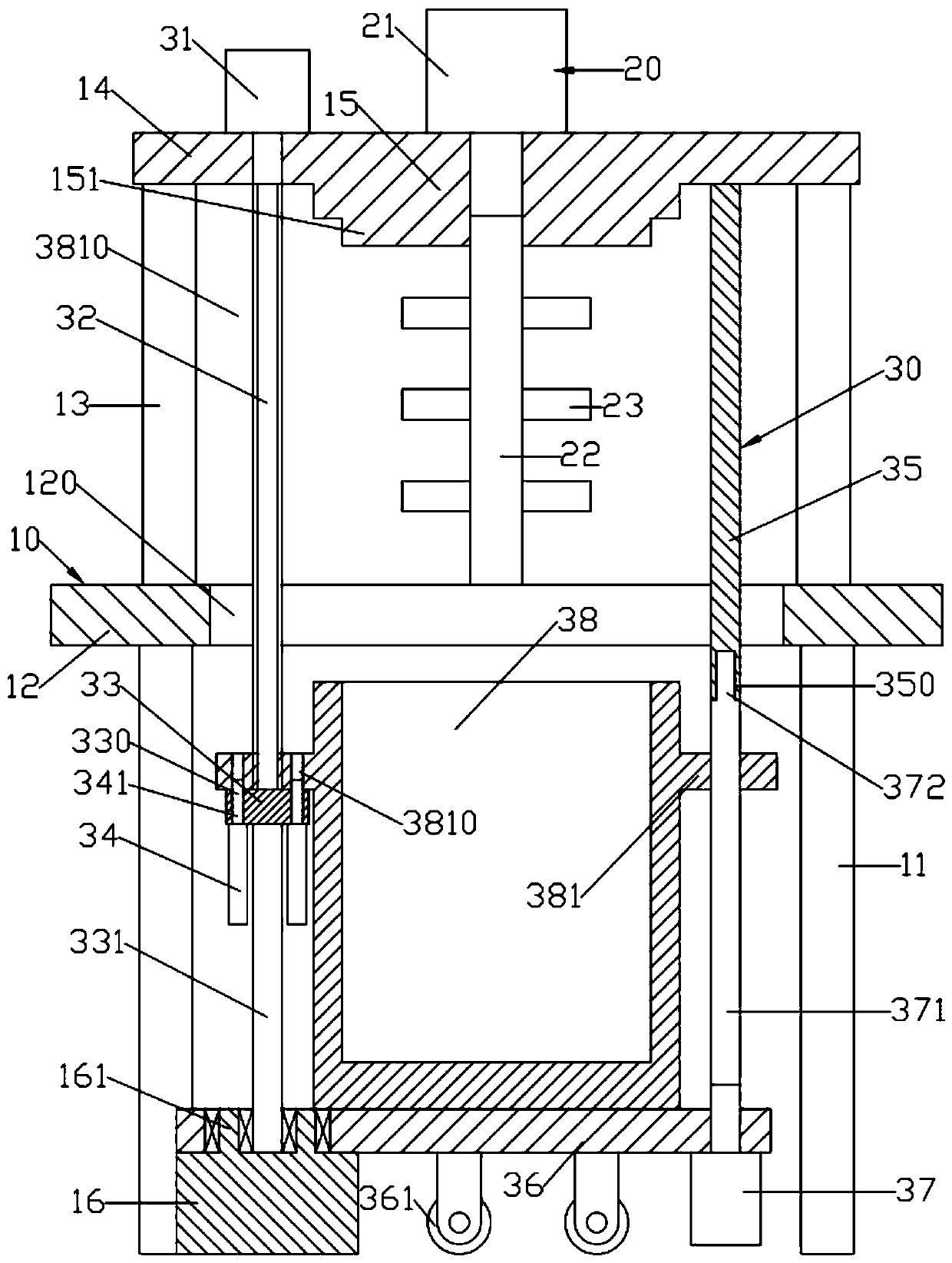
[0016] Such as figure 1 , figure 2 As shown, a pulper for papermaking machinery with convenient feeding and discharging includes a frame 10, a pulping unit 20 and a pulping drum lifting device 30; the frame 10 includes an upper support plate 14, a lower support plate 12 and The bottom support seat 16; the bottom surface center of the upper support plate 14 is provided with an upper closed seat; the pulping unit 20 includes a pulping center column 22; the pulping center column 22 is rotatably arranged on the lower end surface of the upper sealing seat and the pulping center column 22 A pulping blade 23 is formed on the cylindrical surface of the lower support plate; the upper support plate 14 and the lower support plate 12 are connected by a number of evenly distributed vertical links 13; the lower end surface of the lower support plate 12 is provided with a number of support feet 11 And the supporting feet 11 are set on the ground; the center of the lower supporting plate 12 is formed with a lifting and avoiding hole 120 that penetrates up and down; the bottom supporting seat 16 is fixed on the ground; the pulping drum lifting device 30 includes a cylindrical pulping drum 38 with an open upper end And the lifting and rotating device; the lifting and rotating device is located on the frame 10 and is used for lifting and rotating the pulping cylinder 38; when the pulping cylinder 38 is at the uppermost end, the upper closing seat closes the upper end opening of the pulping cylinder 38, and the pulping center The column 22 extends into the pulping drum 38; when the pulping drum 38 is at the uppermost end, the lifting and rotating device drives the pulping drum 38 to rotate.
[0017] Such as figure 1 , figure 2 As shown, the lifting and rotating device includes a lifting threaded rod 32 and an upper right vertical rod 35; the lifting threaded rod 32 is rotatably arranged at the left end of the lower end surface of the upper support plate 14; the upper right vertical rod 35 is fixed at the right end of the lower end surface of the upper support plate 14; The lifting threaded rod 32 and the upper right vertical rod 35 vertically pass through the lifting avoidance hole 120; the lower end of the lifting threaded rod 32 is fixed with the limit support block 33; the lower end of the limit support block 33 is formed with a lower vertical rod 331; the bottom support seat The upper end of the base 16 is formed with a cylindrical upper part 161 of the base; the lower end of the lower vertical rod 331 is pivotally connected to the center of the upper end surface of the upper part of the base 161; the upper part of the base 161 is rotatably provided with a bottom support plate 36; the left end of the bottom support plate 36 is set up and down There is a lower right vertical rod 371; the upper right vertical rod 371 has a connecting rod 372 formed in the center of the upper end surface; the lower right vertical rod 35 is formed with a connecting slot 350 that matches the connecting rod 372; when When the lower right vertical rod 371 is at the far right and the uppermost end, the connecting rod 372 is inserted into the connecting slot 350; the diameter of the lower right vertical rod 371 and the upper right vertical rod 35 are equal; the outer side of the pulping drum 38 The left and right ends of the upper part of the wall are respectively formed with lifting support blocks 381; the lifting support block 381 on the left is screwed on the lifting threaded rod 32; the lifting support block 381 on the right is vertically sleeved on the upper right vertical rod 35; The support block 33 is provided with a limiting device; when the pulping drum 38 is at the lower end, the limiting device makes the left lifting support block 381 and the limiting support block 33 integrated; when the pulping drum 38 is at the lower end, The pulping drum 38 is located below the lower support plate 12, and the right lifting support block 381 is vertically sleeved on the right lower vertical rod 371.
[0018] Such as figure 1 , figure 2 As shown, a lifting cylinder 37 is fixed at the right end of the lower end surface of the bottom support plate 36; the lower right vertical rod 371 is fixed at the upper end of the piston rod of the lifting cylinder 37.
[0019] Such as figure 1 , figure 2 As shown, the bottom surface of the bottom support plate 36 is provided with a number of uniformly distributed universal wheels 361.
[0020] Such as figure 1 , figure 2 As shown, the limiting device includes a number of evenly distributed limiting cylinders 34; the limiting cylinder 34 is fixed on the lower end surface of the limiting support block 33 and the upper end of the piston rod is fixed with a limiting insert 341; the limiting support block 33 is formed with A number of lower limit perforations 330 for the limit insert 341 to pass vertically; the lifting support block 381 on the left is formed with a number of upper limit perforations 3810 for the limit insert 341 to pass vertically; when the pulping drum 38 is in At the bottom end, the upper limit perforation 3810 and the lower limit perforation 330 face each other.
[0021] Such as figure 1 , figure 2 As shown, a pulping motor 21 is fixed at the center of the upper end surface of the upper support plate 14; the upper end of the pulping center column 22 is fixedly connected to the output shaft of the pulping motor 21.
[0022] Such as figure 1 , figure 2 As shown, a lifting rotating motor 31 is fixed on the upper end surface of the upper support plate 14; the upper end of the lifting threaded rod 32 is fixedly connected to the output shaft of the lifting rotating motor 31.
[0023] Such as figure 1 , figure 2 As shown, the upper closed seat includes a cylindrical closed upper part 15 and a closed lower part 151 coaxially arranged; the diameter of the closed upper part 15 is equal to the outer diameter of the pulping drum 38; the diameter of the closed lower part 151 is equal to the inner diameter of the pulping drum 38 .
[0024] The working principle of the pulper for papermaking machinery with convenient feeding and discharging:
[0025] When pulping figure 1 As shown, the pulping cylinder 38 is at the uppermost end, the lower right vertical rod 371 is at the uppermost end, and the limiting insert 341 is at the lower end. At this time, the upper opening of the pulping cylinder 38 is closed by the upper closing seat. 38 is filled with waste paper, the pulping center column 22 rotates, and the pulping blade 23 shreds the paper;
[0026] After the paper shredding is completed, through the rotation of the lifting threaded rod 32, and the guiding action of the upper right vertical rod 35 and the lower right vertical rod 371, the pulping drum 38 is lowered to the lowest end as figure 2 As shown, at this time, the pulping drum 38 is located under the lower support plate 12, and the lifting support block 381 on the right is vertically sleeved on the lower right vertical rod 371, and then the lower right vertical rod 371 is lowered so that the connecting rod 372 Disengage from the connection slot 350, and at the same time, the limit pin 341 rises and inserts into the upper limit hole 3810, so that when the lifting threaded rod 32 rotates again, the pulping cylinder 38 will not fall and will only rotate with the lifting threaded rod 32. The opening of the upper end of the pulping drum 38 is exposed on the front side or the rear side of the frame 10, which facilitates the removal of pulp and the reinsertion of waste paper.
[0027] The above content is only the preferred embodiments of the present invention. For those of ordinary skill in the art, according to the ideas of the present invention, there will be changes in the specific embodiments and the scope of application. limits.