Wild underground water connectivity test device and method

A connectivity test, groundwater technology, applied in measurement devices, machine/structural component testing, fluid dynamics tests, etc., can solve the problems of local groundwater color change, residents panic, etc., to improve accuracy and reduce test costs , the effect of reducing the cost of comprehensive testing

Active Publication Date: 2020-02-14
SHANDONG UNIV +1
View PDF9 Cites 2 Cited by
  • Summary
  • Abstract
  • Description
  • Claims
  • Application Information

AI Technical Summary

Problems solved by technology

However, in the process of studying groundwater hydrogeological parameters, it is found that many research sites are located in densely populated or important water sources, etc., even some low-toxicity tracers will be restricted to use, and fluorescent tracers are easy to cause local Color change in groundwater sparks panic among residents
Therefore, the inventor believes that the conventional method of injecting chemical tracers is gradually unsuitable for densely populated areas or areas with important water sources, and this groundwater connectivity test is necessary

Method used


Image

  • Wild underground water connectivity test device and method

Examples


Embodiment 1

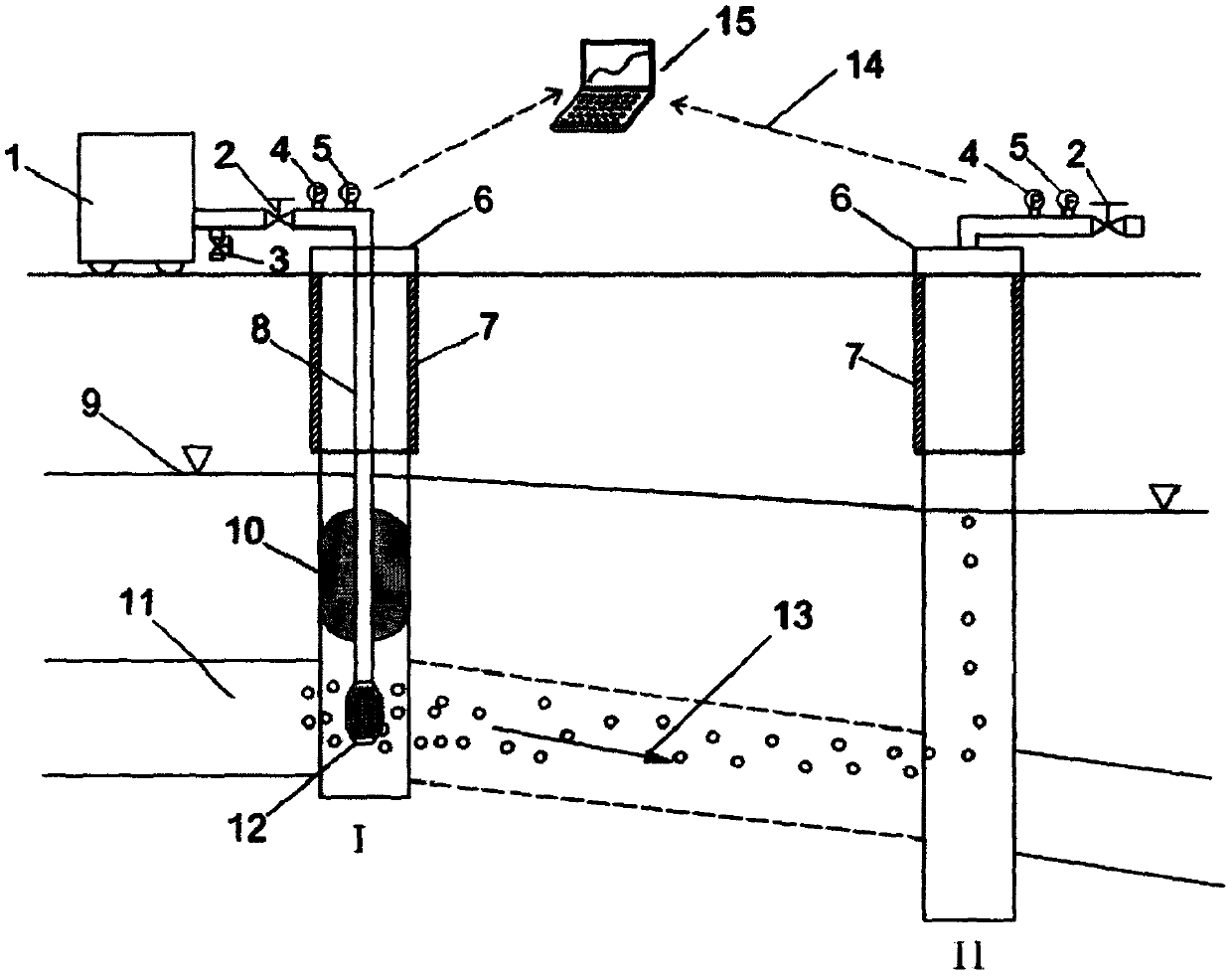
[0027] First, this embodiment discloses a field groundwater connectivity testing device, including a gas pressurization mechanism 1, a valve, a pressure sensor 4, a flow sensor 5, a communicator, a controller 15, a packer 10 and a bubbler 12 , the valve, pressure sensor 4 and flow sensor 5 are installed on the upper side of the injection well 1 well cover 6, the packer 10 and the bubbler 12 are installed on the lower side of the injection well 1 well cover 6, and the gas pressure booster mechanism 1 is communicated with the valve , the controller 15 is connected to the valve, and the pressure sensor 4 and the flow sensor 5 are connected to the controller 15 through a communicator; the gas produced by the gas pressure boosting mechanism 1 can enter the injection well 1 through the valve, the packer 10 and the bubbler 12 It can be understood that the injection well I in this embodiment is an existing injection well I set up for field groundwater connectivity testing, and is not a...

Embodiment 2

[0042] This embodiment discloses a method for testing groundwater connectivity in the field. The gas enters the aquifer 11 from the injection well 1 through the conduit 8 through the valve, the pressure sensor 4, the flow sensor 5, the well cover 6, the packer 10, and the bubbler 12. Once gas enters the monitoring well II, the pressure sensor 4 will send a corresponding pressure rise signal, and the pressure rise signal will be transmitted to the controller 15 through the communicator, and then the controller 15 will control the valve in the monitoring well II to open, so that the gas pressure in the well will Slightly greater than the atmospheric pressure, at this time, the pressure sensor 4 and the flow sensor 5 in the monitoring well II are in continuous communication with the controller 15 through the communicator, and at the same time, the discharged gas samples are regularly taken and the gas component content is analyzed, combined with the pressure sensor 4 and the flow s...


PUM


Abstract

The invention discloses a wild underground water connectivity test device and method. The wild underground water connectivity test device comprises a gasifying-boosting mechanism, a valve, a pressuresensor, a flow sensor, a communicator, a controller, a packer and a bubbler, wherein the valve, the pressure sensor and the flow sensor are arranged on the upper side of an injection well lid; the packer and the bubbler are arranged on the lower side of the injection well lid; the gasifying-boosting mechanism communicates to the valve; the controller is connected with the valve; the pressure sensor and the flow sensor are connected with the controller through the communicator; and gas generated by the gasifying-boosting mechanism can enter an injection well through the valve, the packer and the bubbler. Through the adoption of the wild underground water connectivity test device and method, an external chemical tracer can be prevented from entering the underground water, and meanwhile the connectivity of hydrogeological parameters such as the flow speed, flow direction and the like of the underground water can be indicated.

Description

technical field [0001] The invention relates to the field of groundwater science, in particular to a field groundwater connectivity testing device and method. Background technique [0002] In the field of groundwater science, the groundwater connectivity test is an important test method to grasp the hydrogeological parameters such as groundwater connectivity, flow velocity, and flow direction. Generally, tracers are injected at a certain point upstream, and samples are taken at multiple monitoring points downstream to test the water quality. Method for Tracer Concentration. However, in the process of studying groundwater hydrogeological parameters, it is found that many research sites are located in densely populated or important water sources, etc., even some low-toxicity tracers will be restricted to use, and fluorescent tracers are easy to cause local The color change in the groundwater caused panic among residents. Therefore, the inventor believes that the conventional...

Claims


Application Information

Patent Timeline
Patent Type & Authority Applications(China)
IPC IPC(8): G01M10/00
CPCG01M10/00
Inventor 高帅李常锁贾超李传磊刘文耿付强逄伟
Owner SHANDONG UNIV
Why Eureka
Try Eureka