
Optical fiber transfer box easy to remove dust and dehumidify

A transfer box and optical fiber technology, applied in the direction of light guide, optics, optical components, etc., can solve the problems that affect the normal operation and service life of the components inside the optical fiber transfer box, high humidity, difficult to dehumidify, etc., to achieve enhanced dehumidification effect, Easy to remove dust, easy to disassemble and assemble

Inactive Publication Date: 2020-02-14
湖南彗驰科技有限公司
View PDF8 Cites 1 Cited by
  • Summary
  • Abstract
  • Description
  • Claims
  • Application Information

AI Technical Summary

Problems solved by technology

[0003] However, the above-mentioned technical solution still has the following disadvantages in actual use: it is difficult to dehumidify, and the high humidity will easily affect the normal operation and service life of the internal components of the optical fiber conversion box

Method used


Image

  • Optical fiber transfer box easy to remove dust and dehumidify
  • Optical fiber transfer box easy to remove dust and dehumidify
  • Optical fiber transfer box easy to remove dust and dehumidify

Examples


Embodiment 1

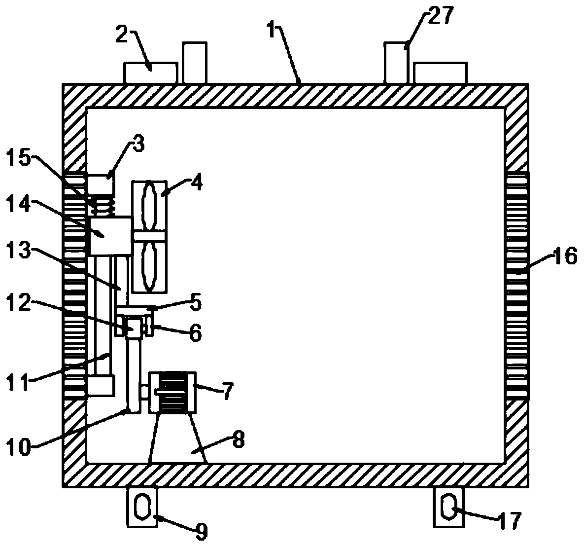
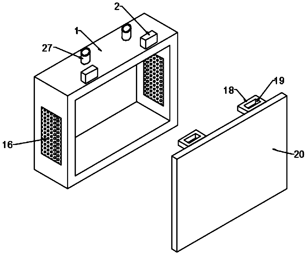
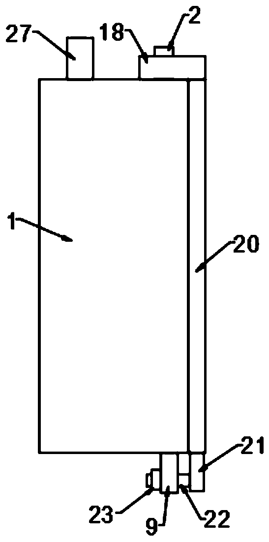
[0028] see Figure 1-3 , in an embodiment of the present invention, an optical fiber transfer box that is easy to remove dust and dehumidify includes a box body 1 and a box cover 20, and a line inlet pipe 27 is provided on the top wall of the box body 1; the box body 1 and the box cover 20 A buckle mechanism is provided on the top, and a ventilation hole 16 is provided on the side wall of the box body 1. A fan 4 is arranged in the box body 1, and a moving mechanism for driving the fan 4 to move is also arranged in the box body 1; The box cover 20 is installed and fixed on the box body 1, and the optical fiber conversion components are installed in the box body 1, the cable passes through the wire inlet pipe 27, and the box cover 20 is removed from the box body 1 to facilitate dust removal; through The cooperation of the fan 4 and the ventilation hole 16 can ventilate, dehumidify, and dissipate heat from the optical fiber adapter components in the box body 1, and then drive the...

Embodiment 2

[0041] see Figure 4 , in the embodiment of the present invention, an optical fiber transfer box that is easy to dedust and dehumidify is different from embodiment 1 in that a third support block 24 is fixed on the side of the box body 1 away from the box cover 20, and the third support block 24 Block 24 is fixed with mounting block 25, and mounting block 25 is provided with mounting hole 26; Through mounting block 25 and mounting hole 26, it is convenient to install and fix casing 1, and fixing bolt is passed mounting hole 26 and gets final product.


PUM


Abstract

The invention relates to the technical field of optical fiber transfer boxes, in particular to an optical fiber transfer box easy to remove dust and dehumidify. The box comprises a box body and a boxcover. Buckling mechanisms are arranged on the box body and the box cover. Vent holes are formed in the side wall of the box body; a fan is arranged in the box body; and a moving mechanism for drivingthe fan to move is also arranged in the box body. According to the invention, an insertion rod and a fixation block cooperate with each other and the insertion rod is inserted into a bar-shaped through hole; the insertion rod can move up and down in the bar-shaped through hole because of the bar-shaped structure of the bar-shaped through hole; after the insertion rod passes through the bar-shapedthrough hole, a clamping tongue is arranged at the upper side of a clamping block and the box cover moves down, so that the clamping block passes through a notch of the clamping tongue; the insertionrod moves down in a nut and then the nut is screwed tightly to complete mounting of the box cover. The box is dismounted or mounted conveniently; the box cover is dismounted from the box body to remove dust conveniently; with the fan and the vent holes, ventilation, dehumidification and heat dissipation can be performed on the optical fiber switching components in the box body.

Description

technical field [0001] The invention relates to the technical field of optical fiber transition boxes, in particular to an optical fiber transition box that is easy to remove dust and dehumidification. Background technique [0002] In the Chinese patent with the authorized announcement number CN208044148U, a backplane-type optical fiber transfer box is disclosed, including a box cover, a backplane, a backplane groove, an inlet, an optical fiber adapter, and an optical fiber fusion splice tray; the backplane includes a horizontal plate The shape is a flat "L" shape; the optical fiber adapter and the optical fiber splicing tray are installed on the horizontal surface of the back plate; the box cover is a cover without the front side wall and the bottom plate The bottom edge of the box cover is provided with a backboard groove for embedding the edge of the horizontal panel of the backboard; the vertical panel of the backboard covers the side of the box cover missing the front s...

Claims


Application Information

Patent Timeline
Patent Type & Authority Applications(China)
IPC IPC(8): G02B6/44
CPCG02B6/4439G02B6/4446G02B6/4454
Inventor 吴何生王小知李金玉王芳
Owner 湖南彗驰科技有限公司
Learn More