Delay test system

A delay test and transmission system technology, applied in the field of image processing, can solve the problem of image transmission system without analysis delay, etc., achieve the effect of low cost, simple system construction, and subtraction of time cost and error

Active Publication Date: 2020-02-14
HUNAN GAOKE ELECTRONICS TECH
View PDF5 Cites 4 Cited by
  • Summary
  • Abstract
  • Description
  • Claims
  • Application Information

AI Technical Summary

Problems solved by technology

[0004] The invention provides a delay test system, aiming to solve the technical problem that there is no scientific method to effectively analyze the delay in the existing image transmission system

Method used


Image

  • Delay test system
  • Delay test system
  • Delay test system

Examples


Embodiment Construction

[0040] specific implementation

[0041] In order to better understand the above technical solutions, the above technical solutions will be described in detail below with reference to the accompanying drawings and specific embodiments.

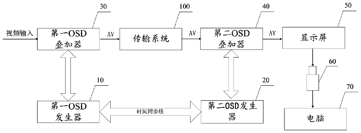
[0042] like figure 1 shown, figure 1 A block diagram of functional modules of the delay test system provided by the present invention. In this embodiment, the delay test system includes a first OSD (on-screen display, on-screen display adjustment mode) generator 10, a second OSD generator 20, the first OSD stacker 30, the second OSD stacker 40, the display screen 50, the camera 60 and the computer 70, wherein the first OSD generator 10 is used to generate the first OSD signal, in the first OSD signal The first time stamp T1 is injected; the second OSD generator 20 is used to generate the second OSD signal, and the second time stamp T2 is injected into the second OSD signal; The transmission system 100 under test is connected, and is used to ...


PUM


Abstract

The invention discloses a delay test system. The system comprises a first OSD generator, a second OSD generator, a first OSD superimposer, a second OSD superimposer, a display screen, a camera and a computer, the first OSD superimposer is used for superimposing a first timestamp injected by the first OSD generator on an input video signal, outputting a character superimposed video signal, and generating transmission information after the character superimposed video signal passes through a to-be-tested transmission system. The second OSD superimposer is used for superimposing a second timestamp injected by the second OSD generator on transmission information generated by the transmission system and outputting a character superimposed video signal; the display screen is used for displayingthe character superimposed video signal output by the second OSD superimposer; the camera is used for shooting the character superimposed video signal displayed on the display screen to generate screen recording data; and the computer is used for identifying the screen recording data generated by the camera and measuring the transmission delay time of the to-be-measured transmission system. The delay test system provided by the invention is high in calculation precision, low in design cost and good in universality.

Description

technical field [0001] The invention relates to the field of image processing, and particularly discloses a time delay test system. Background technique [0002] The application field of image transmission system is getting wider and wider. In the process of developing wireless image transmission system, because the delay of image and data transmission affects the communication quality, the image transmission system cannot fully meet the needs of application scenarios. Therefore, the delay test problem is a general problem in this application area. At present, the action delay on the output display system is observed with the naked eye, or the time difference between two displays is used to measure the delay. However, this is neither accurate nor convenient, and it is difficult to analyze the delay scientifically and effectively. . [0003] Therefore, there is no scientific method to effectively analyze the delay in the existing image transmission system, which is an urgen...

Claims


Application Information

Patent Timeline
Patent Type & Authority Applications(China)
IPC IPC(8): H04N17/00H04N21/8547H04N5/265H04N5/445
CPCH04N5/265H04N5/445H04N17/00H04N21/8547
Inventor 朱晓瑜黄启黄东李婷煜刘华戴科亮黄硕辉谢锋
Owner HUNAN GAOKE ELECTRONICS TECH
Why Eureka
Try Eureka