Cultivation equipment for quickly burying seedling raising cup
A seedling cup, fast technology, applied in the field of seedlings, can solve the problems of large labor time consumption, different excavation diameters, etc., and achieve the effect of simple operation and saving manual operation time
- Summary
- Abstract
- Description
- Claims
- Application Information
AI Technical Summary
Problems solved by technology
Method used
Image
Examples
Embodiment 1
[0020] A kind of seedling cup rapid soil cultivation equipment, such as Figure 1-2 As shown, it includes installation handle 1, placement box 2, installation box 3, vertical movement rod 4, supporting plate 5, lateral movement rod 6, linkage device 7 and soil pulling device 8, installation handle 1 is used to install the equipment inside Parts and holding, the placement box 2 is used for temporarily storing and guiding the seedling cups, the installation box 3 is used to install some parts inside the equipment, the linkage device 7 is used to link the actions in the equipment, and the soil pulling device 8 is used for excavating the soil. Specifically:
[0021] The lower left side of the installation handle 1 is provided with a placement box 2, the lower side of the installation handle 1 is provided with an installation box 3, and the lower side of the installation box 3 is provided with a vertical moving rod 4, and the vertical moving rod 4 extends into The installation box...
Embodiment 2
[0024] On the basis of Example 1, such as image 3 As shown, the linkage device 7 includes a connecting rod 71, a first slide rail 72, a first slider 73, a fixed rod 74, a rack 75, a rotating shaft 76 and a gear 77, specifically:
[0025] The upper side of the vertical movement rod 4 and the right side of the lateral movement rod 6 are provided with a connecting rod 71, the horizontally placed connecting rod 71 is located at the rear side of the vertically placed connecting rod 71, and the front side of the connecting rod 71 is Each is provided with a first slide rail 72, and a first slide block 73 is slidably connected inside the first slide rail 72, and a fixed rod 74 is arranged on the first slide block 73, and the other end of the fixed rod 74 All are connected on the inner wall of the installation box 3, the side wall of the connecting rod 71 is provided with a rack 75, the rear middle part of the inner wall of the installation box 3 is rotatably connected with a rotating...
Embodiment 3
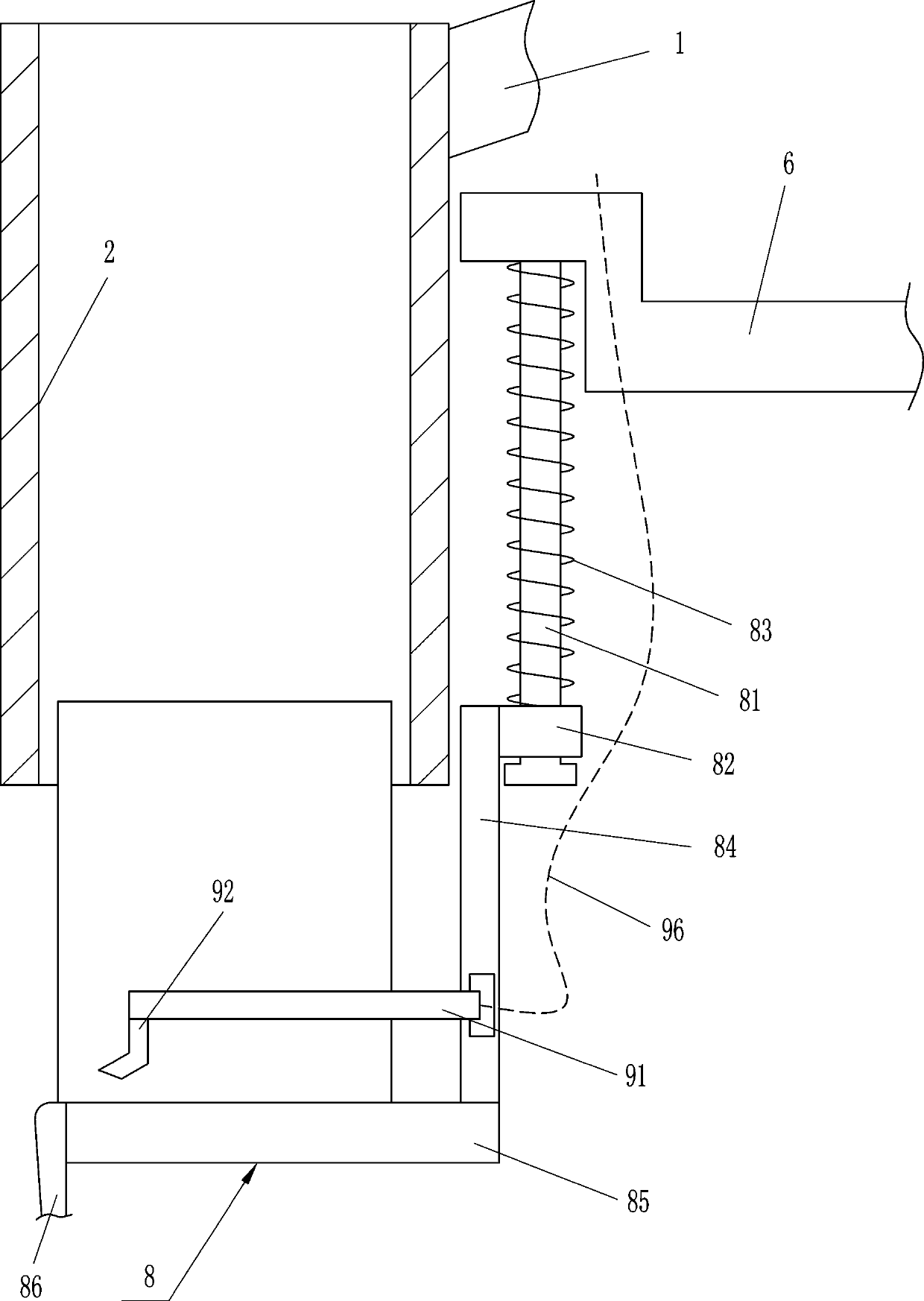
[0028] On the basis of Example 2, such as Figure 4 As shown, the soil pulling device 8 includes a guide rail 81, a guide sleeve 82, a first elastic member 83, a connecting plate 84, a fixed plate 85 and a soil pulling plate 86, specifically:
[0029] A guide rail 81 is provided on the left side of the lower side of the lateral movement rod 6, and a guide sleeve 82 is slidably connected to the guide rail 81, and a first elastic member 83 is connected to the upper side of the guide sleeve 82, and the first elastic member 83 The upper end is connected to the lower side of the laterally moving rod 6, the left side of the guide sleeve 82 is connected with a connecting plate 84, the lower end of the connecting plate 84 is provided with a fixing plate 85, and the left side of the fixing plate 85 is connected with a soil pulling plate 86 .
[0030] In the specific operation of the above-mentioned embodiment, when the seedling cup is placed in the placement box 2, the fixed plate 85 ...
PUM
 Abstract
Description
Claims
Application Information
 - R&D
- Intellectual Property
- Life Sciences
- Materials
- Tech Scout
- Unparalleled Data Quality
- Higher Quality Content
- 60% Fewer Hallucinations
Browse by: Latest US Patents, China's latest patents, Technical Efficacy Thesaurus, Application Domain, Technology Topic, Popular Technical Reports.
© 2025 PatSnap. All rights reserved.Legal|Privacy policy|Modern Slavery Act Transparency Statement|Sitemap|About US| Contact US: help@patsnap.com


