Cooking appliance and pressure-keeping method and device
A technology for cooking utensils and pressure control, which is applied in the direction of cooking utensils, pressure cookers, household utensils, etc. It can solve the problems of poor cooking taste and inability to achieve high-pressure continuous heating, and achieve the effect of improving the cooking taste
- Summary
- Abstract
- Description
- Claims
- Application Information
AI Technical Summary
Problems solved by technology
Method used
Image

Examples
Embodiment 1
[0034] According to an embodiment of the present invention, an embodiment of a method for maintaining pressure control is provided. It should be noted that the steps shown in the flow chart of the accompanying drawings can be executed in a computer system such as a set of computer-executable instructions, and, Although a logical order is shown in the flowcharts, in some cases the steps shown or described may be performed in an order different from that shown or described herein.
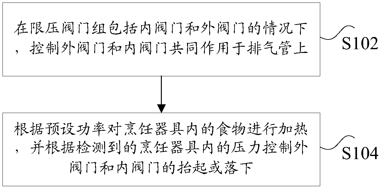
[0035] figure 1 is a schematic flow chart of a method for maintaining pressure control according to an embodiment of the present invention, such as figure 1 As shown, applied to cooking utensils, the method includes the following steps:
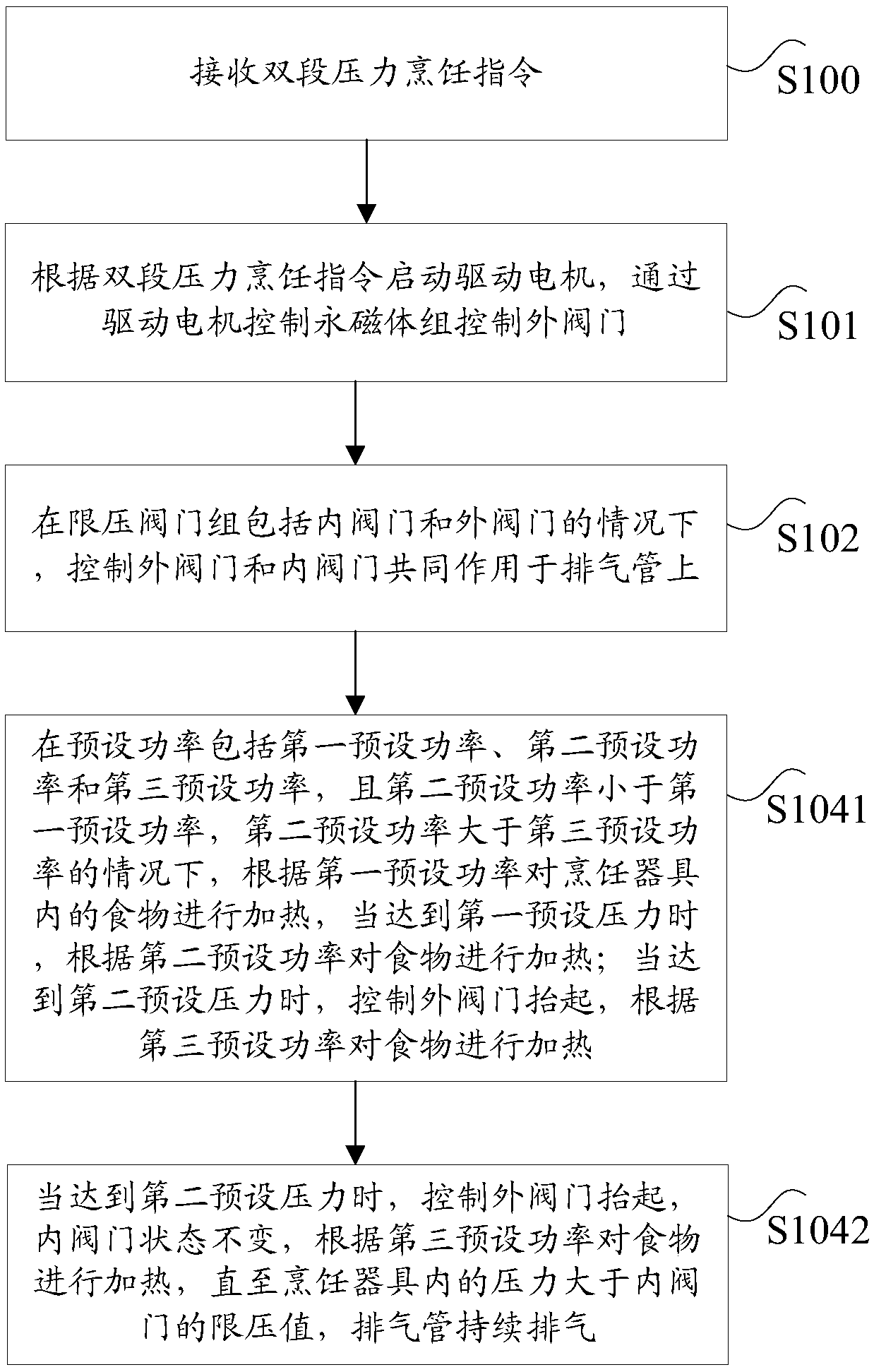
[0036] Step S102, when the pressure limiting valve group includes an inner valve and an outer valve, control the outer valve and the inner valve to act on the exhaust pipe together;
[0037] Step S104, heating the food in the cooking appliance according to the pre...
Embodiment 2
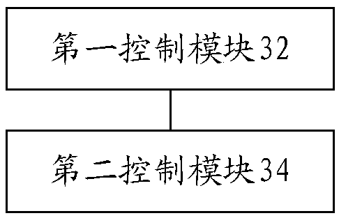
[0063] According to another aspect of the embodiments of the present invention, there is also provided a device for maintaining pressure control, image 3 is a structural schematic diagram of a device for maintaining pressure control according to an embodiment of the present invention, such as image 3 As shown, it is applied to cooking utensils, including: a first control module 32, used to control the outer valve and the inner valve to act on the exhaust pipe together when the pressure limiting valve group includes the inner valve and the outer valve; the second control module 32 The module 34 is used for heating the food in the cooking appliance according to the preset power, and controlling the lifting or lowering of the outer valve and the inner valve according to the detected pressure in the cooking appliance.
[0064] In the embodiment of the present invention, a dual-valve control method is adopted. When the pressure-limiting valve group includes an inner valve and an ...
Embodiment 3
[0066] According to yet another aspect of the embodiments of the present invention, a device for maintaining pressure control is also provided, Figure 4 is a structural schematic diagram of a device for maintaining pressure control according to an embodiment of the present invention, such as Figure 4 As shown, it is applied to cooking utensils, including: a pressure limiting valve group and a lining mechanism; wherein, the pressure limiting valve group includes an inner valve 41 and an outer valve 42, and the inner lining mechanism includes a permanent magnet 13 and a driving motor 44, through which the driving motor 44 Control the permanent magnet 43 to put down the outer valve 42, act on the exhaust pipe 45 together with the inner valve 41, heat the food in the cooking utensil according to the preset power, and control the outer valve 42 according to the detected pressure in the cooking utensil And lift or fall of interior valve 41.
[0067] In the embodiment of the prese...
PUM
 Abstract
Description
Claims
Application Information
 - R&D
- Intellectual Property
- Life Sciences
- Materials
- Tech Scout
- Unparalleled Data Quality
- Higher Quality Content
- 60% Fewer Hallucinations
Browse by: Latest US Patents, China's latest patents, Technical Efficacy Thesaurus, Application Domain, Technology Topic, Popular Technical Reports.
© 2025 PatSnap. All rights reserved.Legal|Privacy policy|Modern Slavery Act Transparency Statement|Sitemap|About US| Contact US: help@patsnap.com