
Circular annular underground culvert pipe construction method

A construction method, circular technology, applied in artificial islands, water conservancy projects, underwater structures, etc., can solve the problems that affect the stability and reliability of the work, the joints are prone to fall off, and the settlement is easy to occur, so as to achieve the guarantee Normal water supply, reduced probability of damage to culverts, and reduced maintenance costs

Inactive Publication Date: 2020-02-18
贵州筑信达创科技有限公司
View PDF7 Cites 1 Cited by
  • Summary
  • Abstract
  • Description
  • Claims
  • Application Information

AI Technical Summary

Problems solved by technology

The structure of the conventional underground culvert is usually a reinforced concrete structure. For the underground structure, in order to ensure its load strength, it is necessary to increase the concrete thickness and the density and diameter of the steel bar, so the cost is high; due to the cumbersome construction of the underground concrete structure, a relatively longer construction period is required At the same time, due to the increase in the thickness of the concrete and the diameter of the steel bar, the weight of the pipe culvert continues to increase, making it prone to settlement, which affects its working stability and reliability, especially when the internal geological structure below the ground changes. , the joints of adjacent culvert pipes are prone to fall off, which affects its working stability and reliability, and it is difficult to overhaul

Method used


Image

  • Circular annular underground culvert pipe construction method
  • Circular annular underground culvert pipe construction method
  • Circular annular underground culvert pipe construction method

Examples


Embodiment Construction

[0028] The technical solutions of the present invention are further described below, but the claimed scope is not limited to the description.

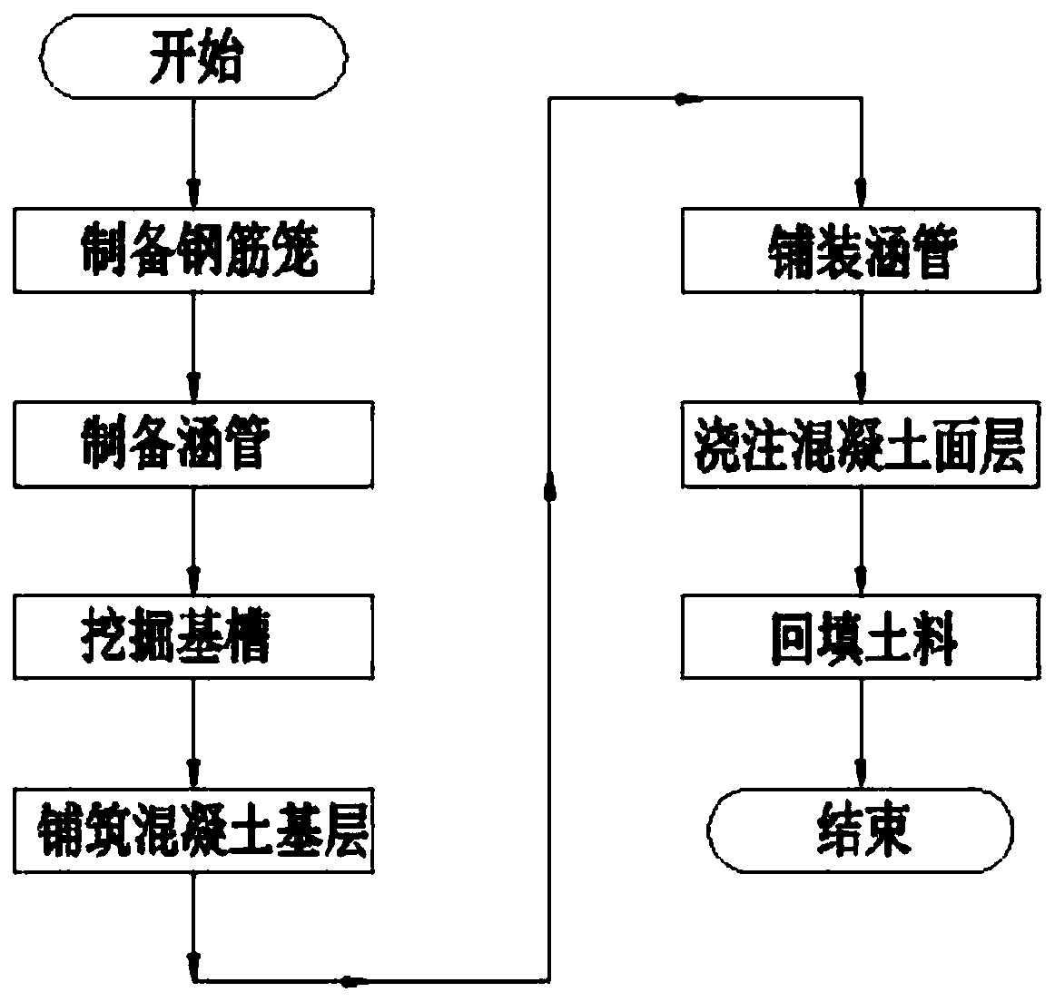
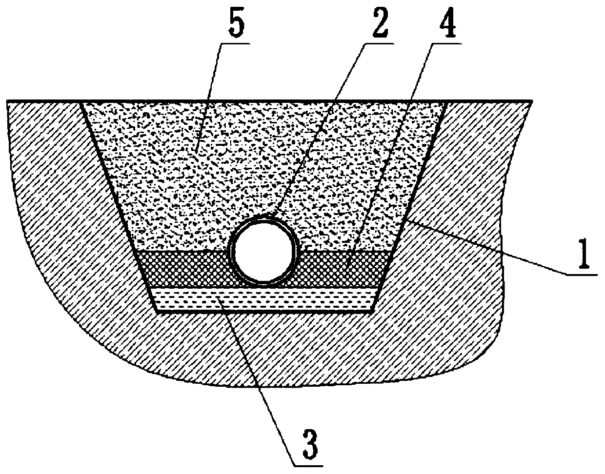
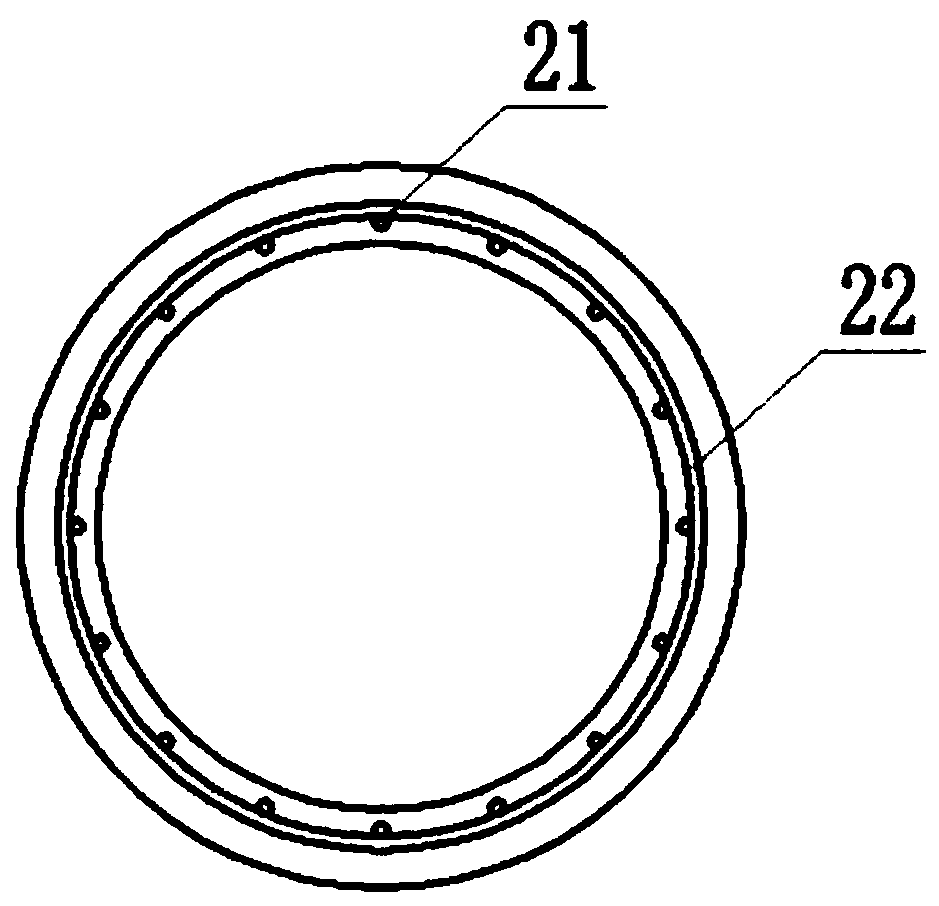
[0029] like figure 1 , figure 2 , image 3 , Figure 4 As shown, the present invention provides a construction method for an annular underground culvert 2, comprising the following steps:

[0030] Step 1: Preparing the reinforcement cage: take the steel bars processed into a circular shape through the bending process as the circumferential stirrups 22, use several straight steel bars as the axial steel bars 21, and first press the circumferential stirrups 22 according to the appropriate The spacing is coaxial and juxtaposed, and the axial steel bars 21 are welded one by one on the inner surface of each circumferential stirrup 22, and the central axis of the axial steel bar 21 is parallel to the central axis of all circumferential stirrups 22. A reinforcing bar cage is prepared; further, in the reinforcing bar cage, the distance be...


PUM


Abstract

The invention provides a circular annular underground culvert pipe construction method. The method comprises the steps of preparing a reinforcement cage, preparing a plurality of culvert pipes, digging a base groove, paving a concrete base layer, paving the culvert pipes, pouring a concrete face layer and backfilling soil. By adopting the technical scheme of the construction method, the length ofthe single culvert pipe is not more than 10 meters, so that the construction process is simplified, the self-weight of each culvert pipe is reduced, and the load on the underground soil layer is reduced; the concrete base layer is connected with the underground soil layer together, so that the load pressure of the underground culvert pipes on the underground soil layer is further reduced, the probability that the underground soil layer generates settlement to damage the culvert pipes is reduced, the structures of the underground culvert pipes are kept stable, the service lives of the underground culvert pipes are prolonged, and the repair and maintenance cost of the underground culvert pipes are reduced; and in addition, every two adjacent culvert pipes are connected together through a rubber gasket ring, so that the stability of the culvert pipe structures is favorably guaranteed when the internal temperature of the underground soil layer is not balanced, and normal water supply, power supply and gas supply of to the residential life are guaranteed.

Description

technical field [0001] The invention relates to the technical field of underground engineering construction, in particular to a construction method for an annular underground culvert. Background technique [0002] Underground culvert is a device used to accommodate various pipelines for water supply, drainage, electricity, telecommunication, optical cable, heat, gas, etc. It connects the above pipeline facilities and is laid below the ground, thereby achieving the purpose of rational and efficient use of underground space. The structure of the conventional underground culvert is usually a reinforced concrete structure. For the underground structure, in order to ensure its load strength, it is necessary to increase the thickness of the concrete and the density and diameter of the steel bars, so the cost is high; due to the cumbersome construction of the underground concrete structure, a relatively longer construction period is required At the same time, due to the increase in...

Claims


Application Information

Patent Timeline
Patent Type & Authority Applications(China)
IPC IPC(8): E02D29/045
CPCE02D29/10
Inventor 胡焰郑鹏吴金儒毛垒王凯黄梅爱何丹
Owner 贵州筑信达创科技有限公司
Learn More