Traceable QFN bracket structure and design method

A technology of bracket structure and design method, which is applied in the direction of semiconductor/solid-state device parts, semiconductor devices, electrical components, etc., can solve problems such as difficulty in tracking the position of a single bracket, achieve small size, improve quality management level, and discharge cloth dispersion effect

Pending Publication Date: 2020-02-18
POWERTECH TECH SUZHOU
View PDF0 Cites 0 Cited by
  • Summary
  • Abstract
  • Description
  • Claims
  • Application Information

AI Technical Summary

Problems solved by technology

[0004] However, if there is no mark on the QFN metal stent, the position of a single stent on the whole stent cannot be tracked after the whole stent is cut into single pieces, which will cause great difficulties in tracing defective products and studying the causes of defects

Method used


Image

  • Traceable QFN bracket structure and design method
  • Traceable QFN bracket structure and design method
  • Traceable QFN bracket structure and design method

Examples


Embodiment 1

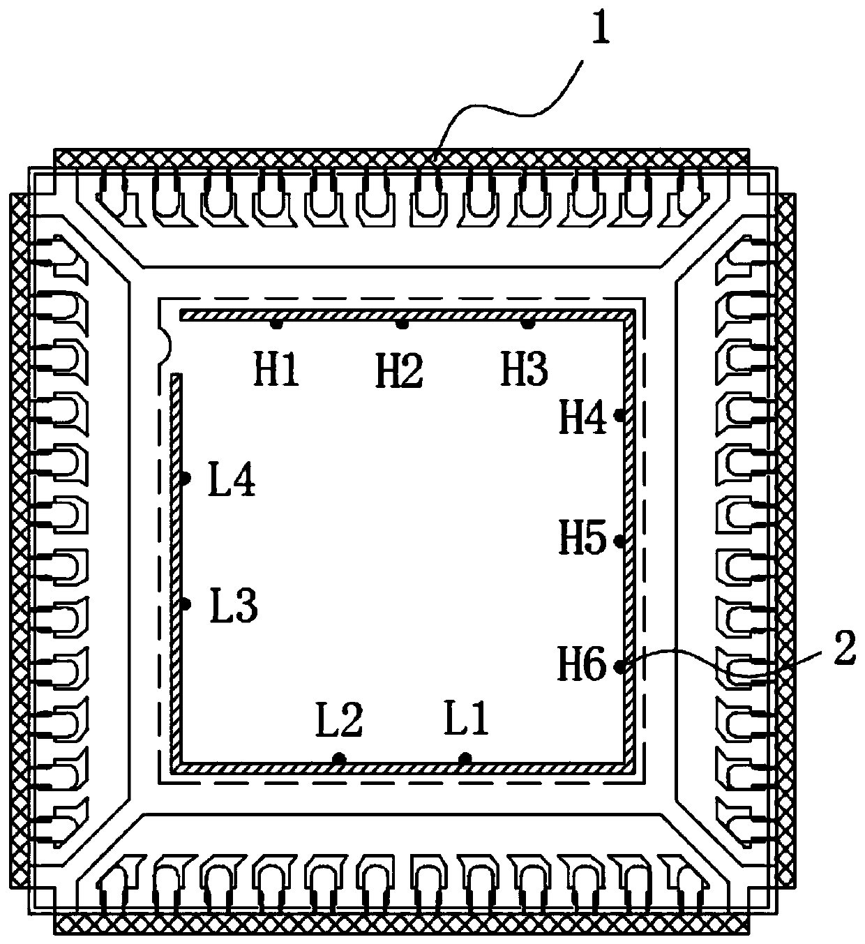
[0031] A traceable QFN scaffold structure, refer to figure 1 , which includes a stent bar (not shown in the accompanying drawings), the stent bar includes several stents 1, the stent 1 is provided with etching marks, and on the stent bars, the etching marks on each support 1 are different; the etching marks include Several etching points 2, and the etching marks are distinguished by the number and position arrangement of etching points 2; in this embodiment, etching points 2 are grooves formed by half etching, wherein the diameter of the groove is greater than 0.08mm and less than 0.12mm, the depth of the groove is greater than 0.08mm and less than 0.12mm, the diameter and depth of the groove in this embodiment are both 0.10mm.

Embodiment 2

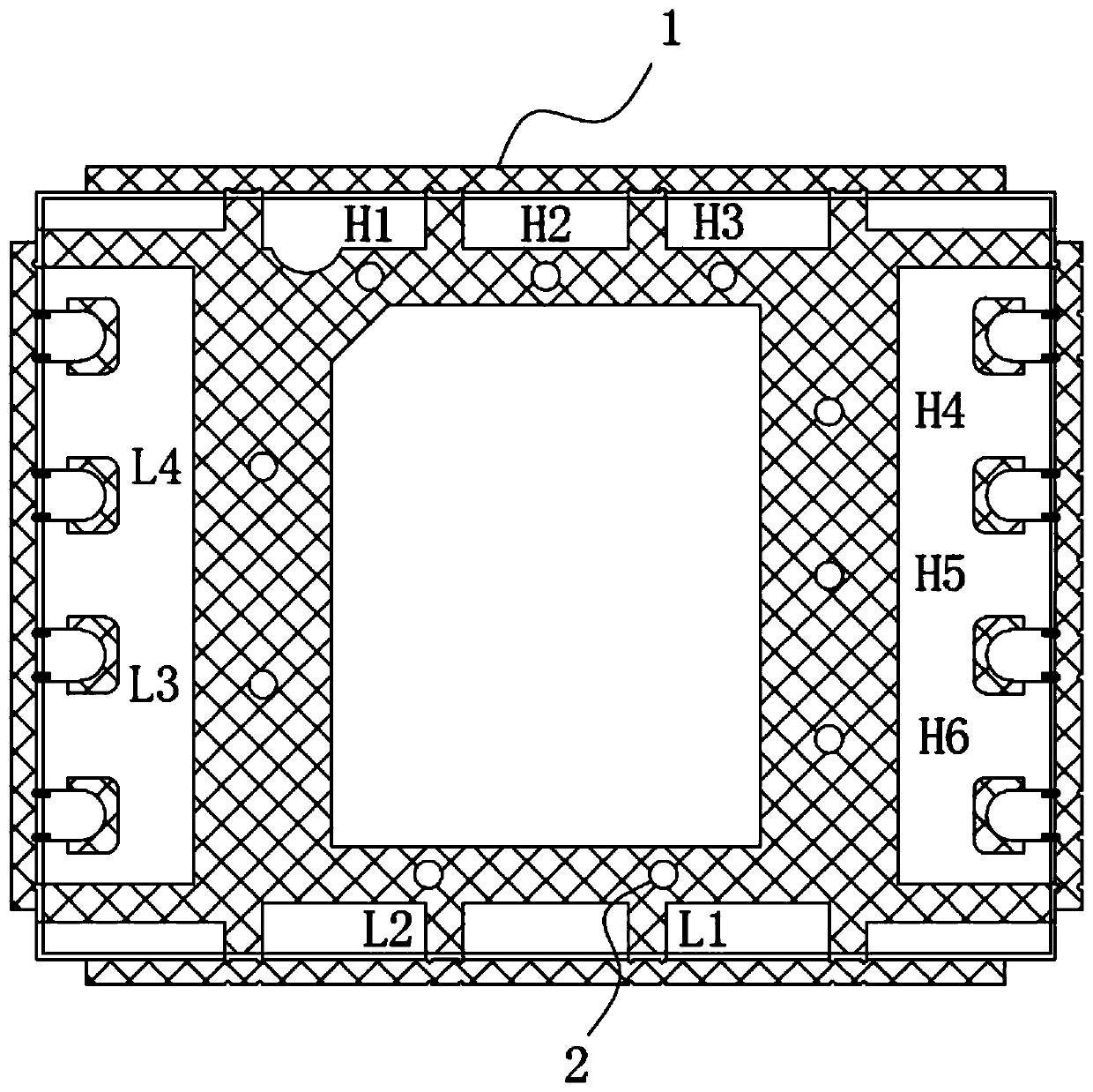
[0033] A traceable QFN scaffold structure, refer to figure 2 , the difference from Example 1 is that the etching point 2 on the bracket 1 in this example is a through hole formed by full etching, wherein the diameter of the through hole is greater than 0.20 mm and less than 0.24 mm, and the diameter of the through hole in this embodiment At the same time, the overall structure of the bracket 1 in the present embodiment is different from that of the bracket 1 in the embodiment 1, but it has no influence, that is, the innovative point of the present invention is applicable to the bracket 1 of various structures.

Embodiment 3

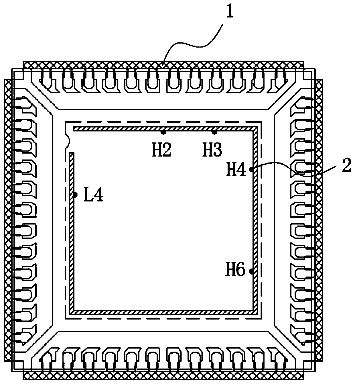
[0035] A traceable QFN stent design method, which includes setting etching marks on a single stent of the stent bar, and making the etching marks on each stent different; the etching marks include several etching points, and define multiple stents on the stent It is used to set the position of etching points, and the etching marks are distinguished by the number and position arrangement of etching points; after the package of the bracket is completed, X-ray irradiation is performed on the package with problems to obtain the X-ray photo of the bracket, and the X-ray photo of the bracket is obtained through X-ray Photophotographs identify the etch marks on the stent and thereby determine the position of the stent on the stent strip.

[0036] refer to figure 1 and figure 2 , the position on the support 1 for setting the etching point 2 includes four single sides arranged in a rectangular shape, each single side defines a plurality of point positions, and the distributed design ...


PUM


Abstract

The invention discloses a traceable QFN bracket structure and a design method and relates to the technical field of QFN package to solve the problem that a conventional QFN bracket has no marks and the position of a single bracket on the entire bracket cannot be determined so as to cause a difficulty in tracing defective products and determining the causes of the defects. The traceable QFN bracketstructure include a bracket bar, which includes a plurality of brackets, wherein each bracket is provided with an etched mark, and the brackets on the bracket bar have different etched marks. The traceable QFN bracket structure can distinguish and display the position of a single bracket on the entire bracket bar, so as to trace the defective products and research the causes of the defects, thereby improving the quality management level.

Description

technical field [0001] The invention relates to the technical field of QFN packaging, more specifically, it relates to a traceable QFN bracket structure and design method. Background technique [0002] QFN (Quad Flat No-lead Package) is a leadless package that is square or rectangular. There is a large area of ​​exposed pad at the center of the bottom of the package for heat conduction, and the package around the large pad There are conductive pads around the periphery to realize the electrical connection. [0003] Considering the versatility of QFN metal stents, there is no extra space on a single stent to design and place corresponding marks. [0004] However, if there is no mark on the QFN metal stent, the position of a single stent on the whole stent cannot be tracked after the whole stent is cut into single pieces, which causes great difficulties in tracing defective products and studying the causes of defects. Contents of the invention [0005] In view of the defic...

Claims


Application Information

Patent Timeline
Patent Type & Authority Applications(China)
IPC IPC(8): H01L23/544H01L23/495
CPCH01L23/49541H01L23/544H01L2223/54433H01L2223/54486
Inventor 金若虚
Owner POWERTECH TECH SUZHOU
Why Eureka
Try Eureka