Clothes supporting rod structure

The technology of a clothes support rod and a clothes support fork is applied in the directions of clothes hangers, clothing, applications, etc., which can solve the problems of clothes falling, and it is not easy to clamp the clothes hanger, etc., and achieves the effects of preventing clothes from falling, low production cost, and simple operation.

Pending Publication Date: 2020-02-21
FUJIAN UNIV OF TECH
0 Cites 0 Cited by

AI-Extracted Technical Summary

Problems solved by technology

It is less likely to catch the hanger an...

Method used

[0021] The corrugated hose 9 on the rod body 1 and sleeved between the upper limit ring 13 and the movable hinge seat 32. The corrugated hose 9 is PP plastic, which is excellent in bending ...

Abstract

The invention discloses a clothes supporting rod structure. The clothes supporting rod structure comprises a rod body and a clothes supporting fork fixedly connected to the top of the rod body, wherein the upper part of the rod body is connected with a clothes hanger, the clothes hanger comprises a fixed hinged seat fixedly connected to the rod body and a movable hinged seat slidably sleeved on the rod body, and an openable and retractable clothes hanger is connected between the fixed hinged seat and the movable hinged seat; the rod body is internally in cup joint with a sliding rod in a sliding mode, a connecting block is fixed on the top of the sliding rod, an avoidance groove arranged in the axial direction is formed in the pipe wall of the rod body, and the connecting block extends outof the avoidance groove to be fixedly connected with the movable hinged seat; a compression spring is arranged in the rod body and at the upper end of the connecting block; a sliding switch is fixedat the bottom of the sliding rod, a sliding chute is formed in the pipe wall of the rod body corresponding to the sliding switch, the sliding switch is connected in the sliding chute in the sliding mode, and a limiting plug which is pluggable and is used for limiting the sliding of the sliding switch is arranged in the sliding chute. By sliding the sliding switch, the stretching of the clothes hanger is controlled, and clothes are prevented from falling onto the ground.

Application Domain

Apparel holders

Technology Topic

Fixed hingeClothes hanger +3

Image

  • Clothes supporting rod structure
  • Clothes supporting rod structure

Examples

  • Experimental program(1)

Example Embodiment

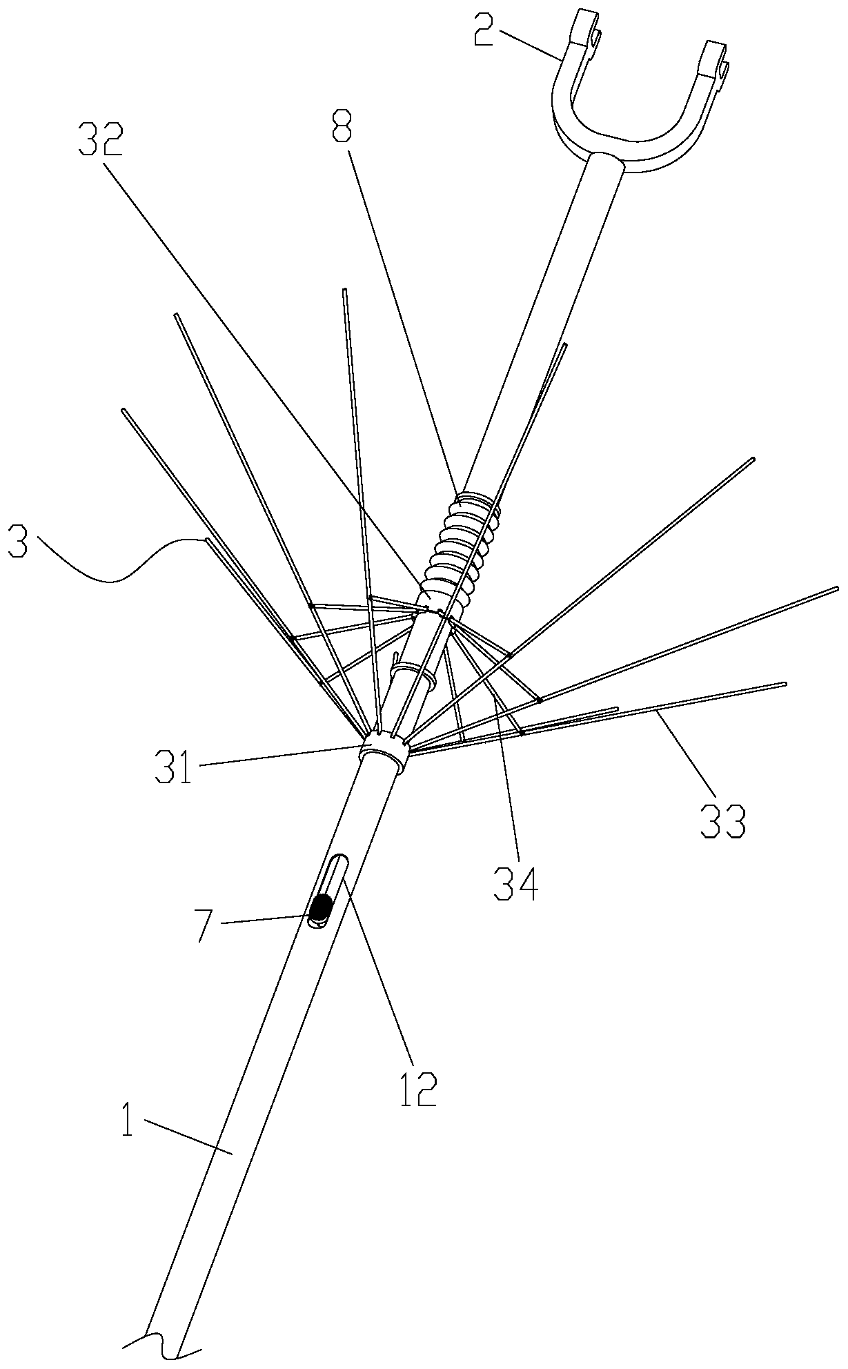
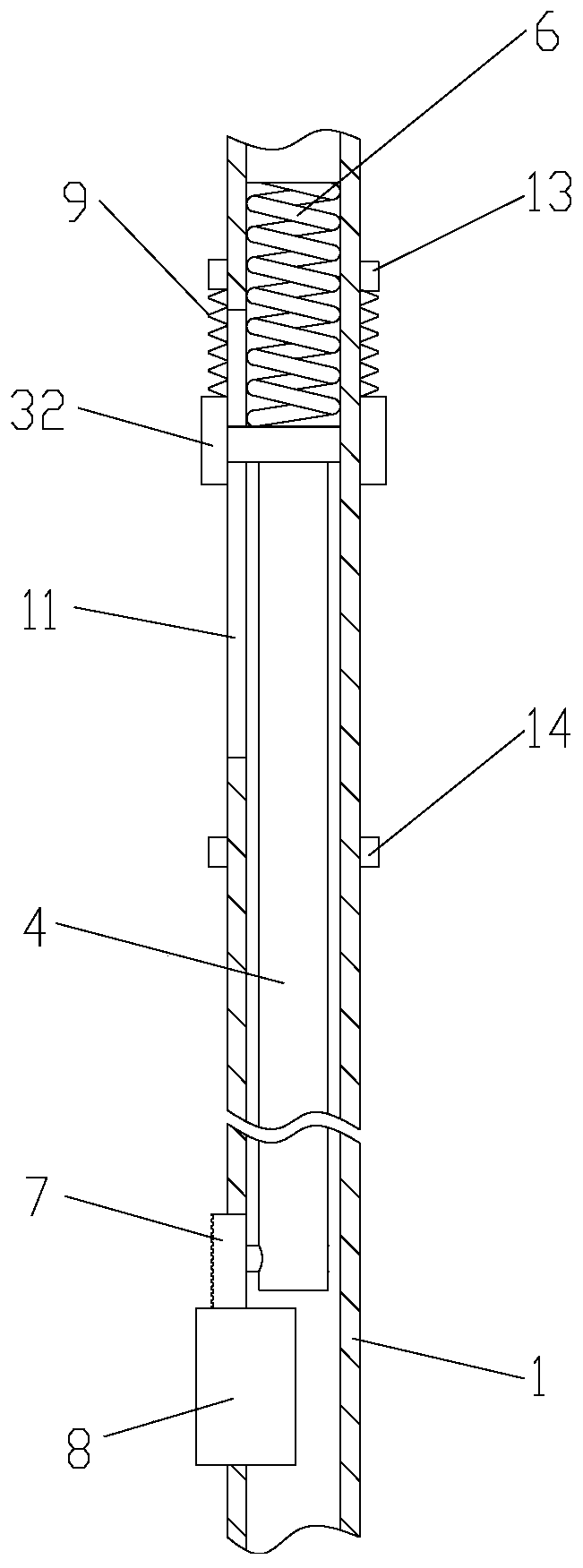
[0018] like figure 1 As shown in or 2, a clothes support rod structure of the present invention includes a rod body 1 and a clothes support fork 2 fixedly connected to the top of the rod body 1, the rod body 1 is a tubular structure, and the upper part of the rod body 1 is connected with a clothes hanger 3, The towing hanger 3 includes a fixed hinged seat 31 fixedly connected to the rod body 1 and a movable hinged seat 32 slidingly sleeved on the rod body 1, and an openable and retractable puller is connected between the fixed hinged seat 31 and the movable hinged seat 32. Clothes hanger 3 is fixed with cloth or film (not shown among the figure, concrete structure is similar to umbrella) on the bottom surface of dragging clothes hanger.
[0019] Described clothes hanger 3 comprises a plurality of long rods 33 that are hinged on the fixed hinged seat 31 at intervals along the circumferential direction. Hinged; the inside of the rod body 1 is slidingly sleeved with a sliding rod 4, the top of the sliding rod 4 is fixed with a connecting block 5, and the pipe wall of the rod body 1 is provided with a relief groove 11 arranged in the axial direction, and the connecting block 5 extends The abdication slot 11 is fixedly connected with the movable hinge seat 32; a compression spring 6 is provided in the rod body 1 and at the upper end of the connection block 5, and the compression spring 6 is pressed against the connection block 5; a slide switch is fixed at the bottom of the slide rod 4 7. There is a chute 12 on the pipe wall of the rod body 1 corresponding to the slide switch 7. The slide switch 7 is slidably connected in the chute 12, and the chute 12 is provided with a pluggable and is used to limit the sliding of the slide switch 7. The limit plug 8.
[0020] An upper limit ring 13 and a lower limit ring 14 are fixed at intervals on the upper part of the rod body 1 , and the movable hinge seat 32 is located between the upper limit ring 13 and the lower limit ring 14 .
[0021] The corrugated hose 9 is sleeved on the rod body 1 and between the upper limit ring 13 and the movable hinge seat 32 . The corrugated hose 9 is PP plastic, which is excellent in bending fatigue resistance. Adopting the bellows to cover the compression spring 6 can prevent the clothes from being soiled by the compression spring 6 or being stuck on the compression spring 6 .
[0022] The clothes fork 2 is thermoformed into a "U" shape by ABS plastic.
[0023] Working principle of the present invention:
[0024] Hold the clothes support bar below the clothes, pull out the limit plug 8, the elastic force of the compression spring 6 is released, the movable hinge seat 32 slides downwards, and drives the clothes hanger 3 to open. When the clothes hanger 3 is opened, each long rod 33 and The rod body 1 is at an angle of 60 degrees, and at this time the movable hinge seat 32 touches the lower stop ring 14;
[0025] When the clothes are collected, if the clothes are accidentally dropped, the dragging hanger 3 will catch the clothes, so as to prevent the clothes from falling on the ground and making the clothes dirty;
[0026] After taking the clothes, slide the slide switch 7 up to the upper limit of the chute 12, the movable hinged seat 32 slides upwards, and drives the dragging hanger 3 to pack up. Bit plug 8 is inserted into chute 12 and gets final product.
[0027] The implementation of the present invention is described above in conjunction with the accompanying drawings, but the present invention is not limited to the above-mentioned specific embodiments, and the above-mentioned specific embodiments are illustrative rather than limiting the present invention, and those of ordinary skill in the art should understand that: it can still be Modify the technical solutions described in the foregoing embodiments, or perform equivalent replacements for some or all of the technical features; and these modifications or replacements do not make the essence of the corresponding technical solutions depart from the scope of the technical solutions of the embodiments of the present invention, All of them should fall within the scope of the claims and description of the present invention.

PUM

no PUM

Description & Claims & Application Information

We can also present the details of the Description, Claims and Application information to help users get a comprehensive understanding of the technical details of the patent, such as background art, summary of invention, brief description of drawings, description of embodiments, and other original content. On the other hand, users can also determine the specific scope of protection of the technology through the list of claims; as well as understand the changes in the life cycle of the technology with the presentation of the patent timeline. Login to view more.

Similar technology patents

Household appliance control method and device and mobile terminal

InactiveCN103605531Aeasy to operateeasy to use
Owner:GD MIDEA AIR-CONDITIONING EQUIP CO LTD +1

Graphene film and preparation method therefor

Owner:CHANGZHOU FUXI TECH CO LTD

Driving working load calculation method of automobile driver

InactiveCN101690666AImprove accuracy and timelinessEasy to operate
Owner:BEIJING UNIV OF TECH

Laser radar optical system with optical axis calibrating function and optical axis calibrating method

InactiveCN102353950AOptical axis alignment with high precisioneasy to operate
Owner:INST OF APPLIED ELECTRONICS CHINA ACAD OF ENG PHYSICS +1

Door body structure of roller washing machine and roller washing machine

PendingCN111979722AImprove space utilizationprevent clothes from falling
Owner:SUZHOU SAMSUNG ELECTRONICS CO LTD +1

Classification and recommendation of technical efficacy words

  • easy to operate
  • prevent clothes from falling

Lancet device

InactiveUS7303573B2inexpensively mass-producedeasy to operate
Owner:ABBOTT DIABETES CARE INC

Rapid and non-invasive optical detection of internal bleeding

InactiveUS20050065436A1easy to operaterapid and accurate result
Owner:HO WINSTON ZONH +2

Door body structure of roller washing machine and roller washing machine

PendingCN111979722AImprove space utilizationprevent clothes from falling
Owner:SUZHOU SAMSUNG ELECTRONICS CO LTD +1
Why Eureka
Try Eureka