Paint spraying mechanical equipment
A mechanical equipment and brushing technology, applied in the direction of spraying devices, liquid spraying devices, etc., can solve the problems of paint solidification, waste of resources, poor spraying effect, etc., and achieve uniform coating, convenient spraying, and good spraying effect Effect
- Summary
- Abstract
- Description
- Claims
- Application Information
AI Technical Summary
Problems solved by technology
Method used
Image

Examples
Embodiment 1
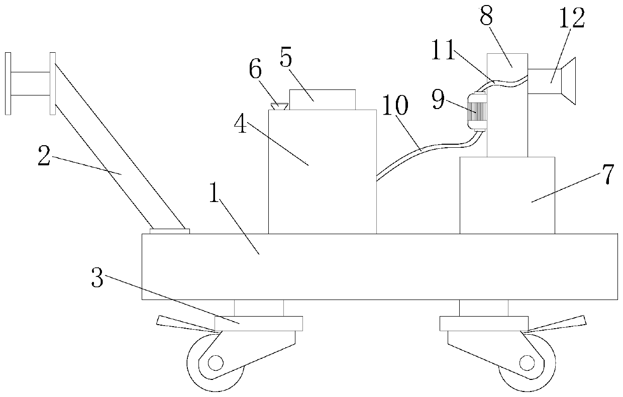
[0027] refer to Figure 1-6 , a paint spraying mechanical equipment is proposed in this embodiment, comprising a base 1, a stirring box 4 is fixedly connected to the top of the base 1, a power seat 5 is fixedly connected to the top of the stirring box 4, and a stirring assembly is arranged on the power seat 5 , the top of the mixing box 4 is sealed and fixedly connected with the feed funnel 6, the top of the base 1 is fixedly connected with the adjustment seat 7, the adjustment seat 7 is provided with a lifting assembly, the lifting assembly is connected with a fixed plate 8, and one part of the fixed plate 8 The side is fixedly connected with a liquid pump 9, the input end of the liquid pump 9 is sealed and fixedly connected with a hose 10, one end of the hose 10 is sealed and fixedly connected with one side of the mixing tank 4, and the output end of the liquid pump 9 is sealed and fixedly connected with a The connecting pipe 11 is provided with a nozzle 12 on the other side...
Embodiment 2
[0029]In this embodiment, universal wheels 3 are provided at the four corners of the bottom of the base 1, and a handle 2 is fixedly connected to the top of the base 1. The handle 2 and the universal wheels 3 are provided to make the device easy to move and increase convenience.
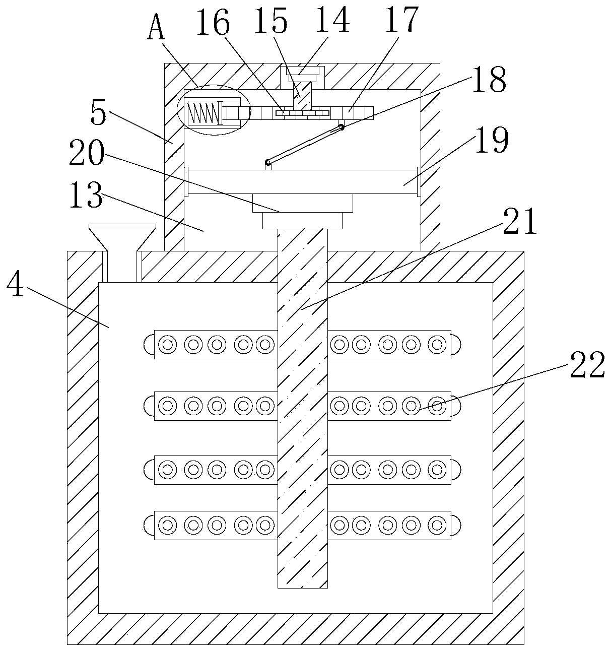
[0030] In this embodiment, the mixing assembly includes a power tank 13 provided at the bottom of the power base 5, a first motor 14 is fixedly connected to the inner wall of the top of the power tank 13, and a rotating shaft 15 is fixedly connected to the output shaft of the first motor 14. The rotating shaft 15 The bottom end fixed cover is provided with gear 16, and gear 16 is meshed with rack 17, and the bottom of rack 17 is connected with rotating bar 18, and slide plate 19 is slidably connected in power tank 13, and one end of rotating bar 18 and sliding plate The top of 19 is rotationally connected, and the bottom of sliding plate 19 is fixedly connected with second motor 20, and the output sha...
PUM
 Abstract
Description
Claims
Application Information
 - Generate Ideas
- Intellectual Property
- Life Sciences
- Materials
- Tech Scout
- Unparalleled Data Quality
- Higher Quality Content
- 60% Fewer Hallucinations
Browse by: Latest US Patents, China's latest patents, Technical Efficacy Thesaurus, Application Domain, Technology Topic, Popular Technical Reports.
© 2025 PatSnap. All rights reserved.Legal|Privacy policy|Modern Slavery Act Transparency Statement|Sitemap|About US| Contact US: help@patsnap.com