Oven structure for flocking machine

A technology of flocking machine and oven, which is applied to the surface coating liquid device, pretreatment surface, coating, etc., which can solve the problems of glue solidification and affecting flocking effect

Inactive Publication Date: 2020-02-21
WUXI QUANSHUN MACHINERY MFG
View PDF0 Cites 0 Cited by
  • Summary
  • Abstract
  • Description
  • Claims
  • Application Information

AI Technical Summary

Problems solved by technology

When the flocking machine is in use, the fleece cloth passes through the gluing equipment through the reciprocating conveyor chain 1-4 for gluing, and then passes through the falling equipment when the cloth is covered with fluff, and then passes through the oven for heating. The traditional structure, combined with figure 2 As shown, the conveyor chain 1-4 conveyor section 1-41 and return section 1-42 are both in the oven, so that the heat in the oven will be transferred to the glue coating equipment through the return section 1-42, resulting in too fast glue Solidification, affect the flocking effect

Method used


Image

  • Oven structure for flocking machine
  • Oven structure for flocking machine
  • Oven structure for flocking machine

Examples


Embodiment Construction

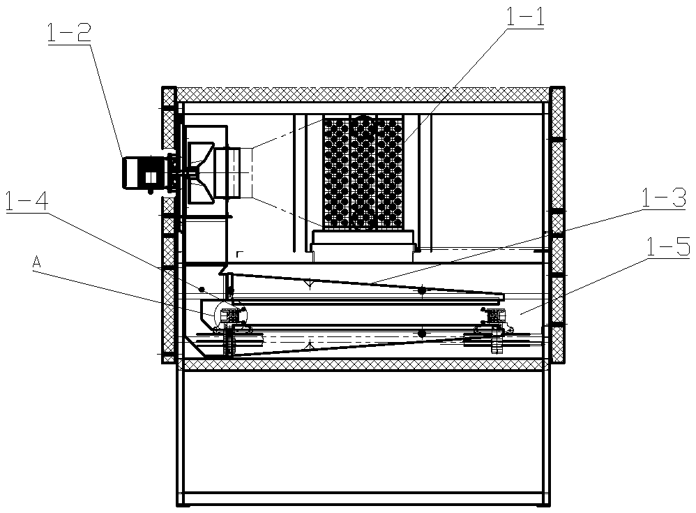
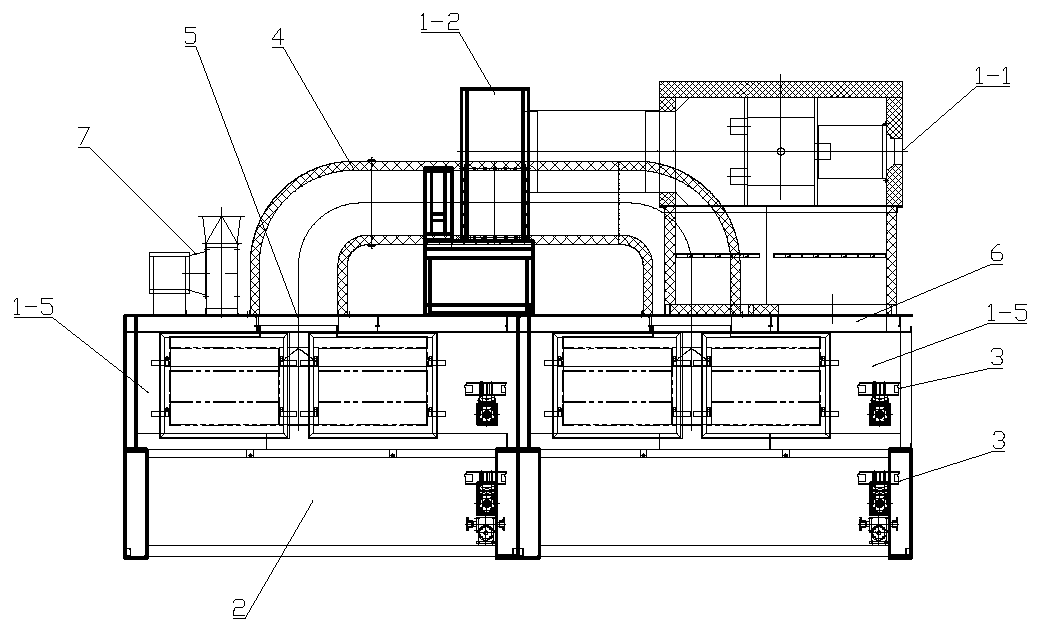
[0017] Such as image 3 , Figure 4 The shown oven structure for the flocking machine includes a heating device 1-1, a blower fan 1-2, and a heating chamber 1-5. The heating chamber 1-5 is equipped with a wind deflector 1-3, loaded with flocking The conveyor chain 1-4 of the base material is set through the heating chamber 1-5, which also includes an isolation chamber 2 separated from the heating chamber 1-5, and the conveyor chain 1 not loaded with the flocking substrate returned by the flocking machine end point -4 is set through the isolation chamber 2, the heating chamber 1-5 and the isolation chamber 2 are respectively equipped with guide rails 3 for guiding the conveyor chain 1-4, the isolation chamber 2 is located at the bottom of the heating chamber 1-5, the isolation chamber 2 and the heating chamber 1-5 are separated by insulation materials such as asbestos.

[0018] After adopting such a structure, the conveyor chain 1-4 returned by the end point of the flocking m...


PUM


Abstract

The invention provides an oven structure for a flocking machine. The oven structure does not transfer the heat of an oven to gluing equipment, so that too fast solidification of glue is avoided. The oven structure comprises a heating device, a fan and a heating chamber, wherein an air guide plate is arranged in the heating chamber, and a conveying chain loaded with a flocking base material is arranged penetrating through the heating chamber; and the oven structure further comprises an isolation chamber separated from the heating chamber, and the conveying chain returned from the end point of the flocking machine and not loaded with the flocking base material is arranged penetrating through the isolation chamber.

Description

technical field [0001] The invention relates to the technical field of flocking equipment, in particular to an oven structure for a flocking machine. Background technique [0002] The flocking machine is used to vertically fix the fluff on the substrate coated with adhesive. During the flocking process, an oven is required to solidify the adhesive. The traditional oven structure is as follows: figure 1 As shown, it includes a heating device 1-1 and a blower 1-2. The heat generated by the heating device 1-1 is blown into the heating chamber 1-5 through the blower 1-2, and the heat generated by the heating device 1-1 is blown into the heating chamber 1-5 Wind deflector 1-3 blows to fluffy cloth. When the flocking machine is in use, the fleece cloth passes through the gluing equipment through the reciprocating conveyor chain 1-4 for gluing, and then passes through the falling equipment when the cloth is covered with fluff, and then passes through the oven for heating. The trad...

Claims


Application Information

Patent Timeline
Patent Type & Authority Applications(China)
IPC IPC(8): B05D3/04
CPCB05D3/0413
Inventor 张裕良
Owner WUXI QUANSHUN MACHINERY MFG
Why Eureka
Try Eureka