Method for preparing nickel-based superalloy Rene80 directionally-grown column crystal/single crystal alloy and manufacturing parts

A nickel-based superalloy, directional growth technology, applied in the directions of crystal growth, single crystal growth, single crystal growth, etc., can solve the problems of long manufacturing time and low yield, reduce manufacturing costs, improve utilization, shorten the The effect of the manufacturing cycle

Inactive Publication Date: 2014-03-26
BEIJING UNIV OF TECH
View PDF3 Cites 23 Cited by
  • Summary
  • Abstract
  • Description
  • Claims
  • Application Information

AI Technical Summary

Problems solved by technology

[0006] However, the main problems in the production of directionally solidified blades and single crystal blades are long manufacturing time and low yield.
There is no precedent in the

Method used


Image

  • Method for preparing nickel-based superalloy Rene80 directionally-grown column crystal/single crystal alloy and manufacturing parts
  • Method for preparing nickel-based superalloy Rene80 directionally-grown column crystal/single crystal alloy and manufacturing parts
  • Method for preparing nickel-based superalloy Rene80 directionally-grown column crystal/single crystal alloy and manufacturing parts

Examples


Embodiment 1

[0048] (1) Preparation of directional growth columnar crystals and single crystal alloys by laser beam continuous melting deposition

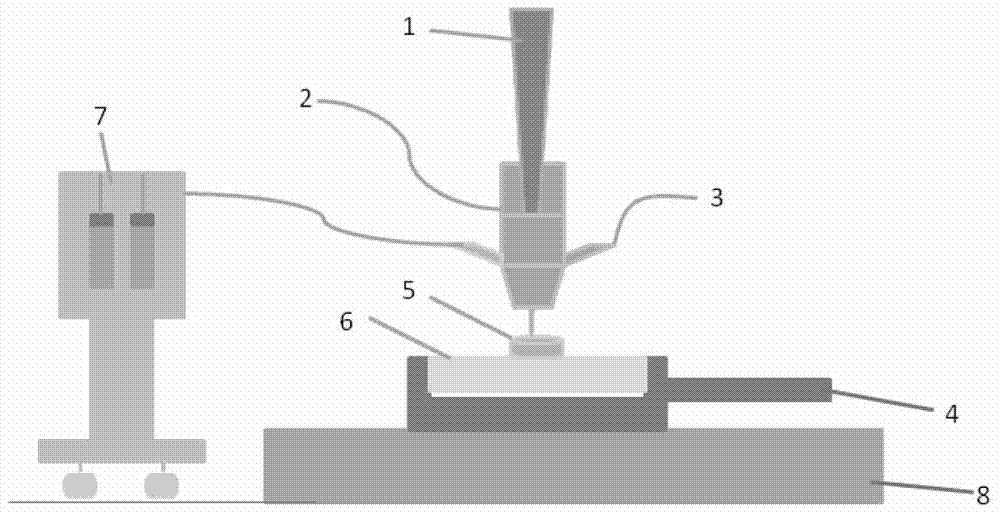
[0049] The bottom plate used in the experiment is Rene142 directionally solidified nickel-based alloy, and the thickness of the bottom plate is 2mm. The selected laser processing equipment is CO 2 The laser (maximum output power is 6KW), the laser wavelength is 1064nm, the focal length of the selected focusing lens is 270mm, the radius of the focal spot is 0.69mm, and the surface of the base plate is located at the focal plane of the laser.

[0050] The crystal orientation of the base plate is parallel to the forming direction of the part in the part manufacturing process. First set important parameters: laser power 600W, laser movement speed 200mm / min, powder feeding speed 10g / m, protective gas flow 25L / min, carrier gas flow 15L / min, z-axis displacement 350um. Then turn on the gas feeding and powder feeding devices, and start the high-energy...

Embodiment 2

[0053] (2) Preparation of directional growth columnar crystals and single crystal alloys by laser beam continuous melting deposition

[0054] The bottom plate used in the experiment is Rene142 directionally solidified nickel-based alloy, and the thickness of the weldment is 2mm. The selected laser processing equipment is CO 2 The laser (maximum output power is 6KW), the laser wavelength is 1064nm, the focal length of the selected focusing lens is 270mm, the radius of the focal spot is 0.69mm, and the surface of the base plate is located at the focal plane of the laser.

[0055] The substrate crystal orientation is perpendicular to the forming direction of the part during part fabrication. First set important parameters: laser power 600W, laser movement speed 200mm / min, powder feeding speed 10g / m, protective gas flow 25L / min, carrier gas flow 15L / min, z-axis displacement 350um. Then turn on the gas feeding and powder feeding devices, and start the high-energy beam. At this t...


PUM

PropertyMeasurementUnit
Thicknessaaaaaaaaaa

Abstract

The invention relates to a method for preparing a nickel-based superalloy Rene80 directionally-grown column crystal/single crystal alloy and manufacturing parts, and belongs to the processing field of the laser materials. The method is carried out in atmosphere; a high-energy beam is taken as the heat source; the movement of the high-energy beam is achieved under the control of a numerical control system; the Rene80 powder flow conveyed by a carrier gas is smelted and deposited on a directionally-solidified nickel-based alloy substrate layer by layer; in this way, the nickel-based superalloy and parts having directionally-grown straight column crystal structure/single crystals and different cross-section shapes can be directly manufactured. The nickel-based alloy Rene80 directionally-grown column crystal/single crystal alloy parts manufactured by the method can be applied to manufacturing the hot end parts of naval ships, gas turbines and aero-engines.

Description

technical field [0001] The invention relates to a method for preparing directional growth columnar crystals and single crystal alloys and parts, in particular to a method for manufacturing directional growth columnar crystals and parts with arbitrary shapes by layer-by-layer deposition of continuously conveyed powder. Background technique [0002] Directional solidification is a casting technology that uses the principle that grains grow in the opposite direction of heat flow when the alloy solidifies, controls the direction of heat flow, and makes the casting crystallize in a specified direction. Ordinary castings are generally composed of polycrystals without a certain crystallization direction. The most prominent achievement of directional solidification technology is its application in the aviation industry. Using directional solidification technology can produce thin-walled hollow turbine blades with excellent thermal shock resistance, long fatigue life, good creep res...

Claims


Application Information

Patent Timeline
IPC IPC(8): C30B29/52C30B21/00B22F3/115B22F3/105
Inventor 张冬云李志波赵恒吴瑞
Owner BEIJING UNIV OF TECH
Why Eureka
Try Eureka