Thin plate cutting device

A cutting and thin plate technology, applied in feeding devices, metal processing machinery parts, metal processing equipment, etc., can solve the problems of poor smoothness, high working intensity, and uneven incision of thin plates

Inactive Publication Date: 2020-02-21
马鞍山楚锐科技信息咨询有限公司
View PDF15 Cites 0 Cited by
  • Summary
  • Abstract
  • Description
  • Claims
  • Application Information

AI Technical Summary

Problems solved by technology

[0002] At present, the cutting method for the thin plate is: first draw the line and then use scissors to cut the thin plate along the extension direction of the drawn line, such as cutting the aluminum alloy thin plate. The cut of the thin plate cut in this way is uneven and smooth. Poor performance, high work intensity

Method used


Image

  • Thin plate cutting device

Examples


Embodiment Construction

[0021] Specific embodiments of the present invention will be described in detail below in conjunction with the accompanying drawings. It should be understood that the specific embodiments described here are only used to illustrate and explain the present invention, and are not intended to limit the present invention.

[0022] In the present invention, unless otherwise specified, the orientation words included in the term such as "up, down, left, right, front, back, inside and outside" only represent the orientation of the term in the normal use state, or the common name understood by those skilled in the art. , and should not be construed as a limitation of this term.

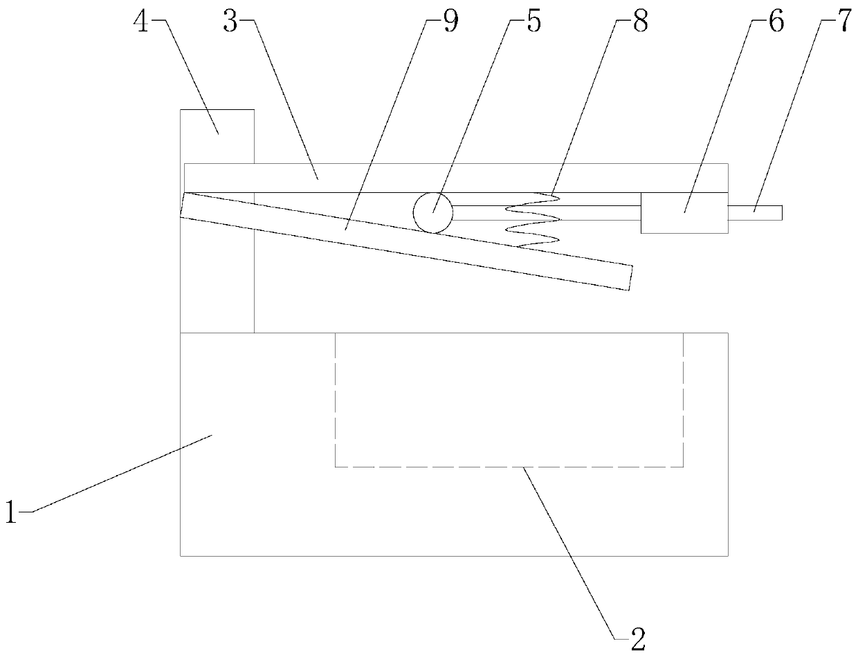
[0023] see figure 1 The thin plate cutting device shown includes: an operation table 1, on which a stand 4 and a cutting groove 2 are arranged, and a crossbeam 3 is fixedly connected to the stand 4, and the The stand 4 is hinged with a cutter 9 below the beam 3, and the stand 4 is provided with a drive mechan...


PUM


Abstract

The invention discloses a thin plate cutting device. The thin plate cutting device comprises an operation table, wherein a vertical frame and a cutting groove are arranged on the operation table; a cross beam is fixedly connected to the vertical frame; a cutter is hinged to the position, positioned below the cross beam, of the vertical frame; a driving mechanism for driving the cutter to swing isarranged on the vertical frame; and the driving mechanism drives the end part of the cutter to extend into or extend out of the cutting groove. According to the thin plate cutting device, manual cutting can be simulated, a thin plate is cut from one side to the other side, the cutting effect is good, and the smoothness is good.

Description

technical field [0001] The present invention relates to a cutting device, in particular to a sheet cutting device. Background technique [0002] At present, the cutting method for the thin plate is: first draw the line and then use scissors to cut the thin plate along the extension direction of the drawn line, such as cutting the aluminum alloy thin plate. The cut of the thin plate cut in this way is uneven and smooth. Poor performance, high work intensity. Contents of the invention [0003] The purpose of the present invention is to provide a thin plate cutting device, which can simulate manual cutting and cut the thin plate from one side to the other side, with good cutting effect and smoothness. [0004] In order to achieve the above object, the present invention provides a thin plate cutting device, which includes: an operation table, on which a stand and a slot are arranged, and a crossbeam is fixedly connected to the stand, A cutting knife is hinged below the beam ...

Claims


Application Information

Patent Timeline
IPC IPC(8): B23D79/00B23Q5/22
CPCB23D79/00B23Q5/22
Inventor 李波
Owner 马鞍山楚锐科技信息咨询有限公司
Why Eureka
Try Eureka