Clamping mechanism of cross beam welding fixture

A welding jig and clamping mechanism technology, which is applied in welding equipment, auxiliary welding equipment, welding/cutting auxiliary equipment, etc., can solve the problems of inability to guarantee the quality of the weld, welding deviation, high scrap rate, etc., so as not to affect the welding quality , control welding deformation, improve the effect of quality status

Inactive Publication Date: 2020-02-21
WUHU POWER TECH
View PDF7 Cites 0 Cited by
  • Summary
  • Abstract
  • Description
  • Claims
  • Application Information

AI Technical Summary

Problems solved by technology

[0002] The use of welding fixtures adapted to the product structure in modern welding production plays a very important role in improving product quality, reducing labor intensity of workers, and accelerating welding production to achieve mechanization and automation. Or through a simple self-made positioning plate or manual positioning, the quality of the weld cannot be guaranteed during welding, and looseness is likely to occur during welding, resulting in welding deviation, resulting in a high scrap rate, so it is very important to solve this problem

Method used


Image

  • Clamping mechanism of cross beam welding fixture
  • Clamping mechanism of cross beam welding fixture

Examples


Embodiment Construction

[0012] In order to deepen the understanding of the present invention, the present invention will be described in further detail below with reference to the embodiments, which are only used to explain the present invention and do not constitute a limitation on the protection scope of the present invention.

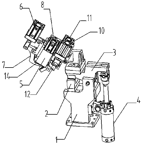
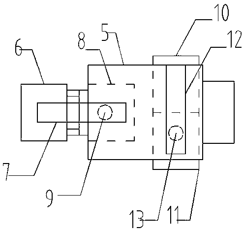
[0013] like Figure 1-2 As shown, this embodiment provides a clamping mechanism for a beam welding fixture, including a base 1, a clamp block 2 is provided on the left side of the upper end of the base 1, a rotating arm 3 is connected to the right side of the upper end of the base 1 through a shaft pin, and the right side of the base 1 is provided with There is a turning cylinder 4, the left side of the turning cylinder 4 is connected to the base 1 through a shaft pin, the upper end of the turning cylinder 4 is connected to the right end of the rotating arm 3 through a shaft pin, the left end of the rotating arm 4 is connected to the mounting plate 5, and the left side of th...


PUM


Abstract

The invention provides a clamping mechanism of a cross beam welding fixture. The clamping mechanism comprises a base, wherein a fixture block is arranged on the left side of the upper end of the base;the right side of the upper end of the base is connected with a rotating arm through a shaft pin; an overturning cylinder is arranged on the right side of the base; the left side of the overturning cylinder is connected with the base through a shaft pin; the upper end of the overturning cylinder is connected with the right end of the rotating arm through a shaft pin; the left end of the rotatingarm is connected with a mounting plate; a first cylinder is arranged on the left side of the mounting plate; the lower end of the first cylinder is connected with a first pressing arm through a shaftpin; a second cylinder is arranged in the middle of the mounting plate; the lower end of the second cylinder is connected with a first pressing point; a third cylinder and a fourth cylinder are arranged on the right side of the mounting plate; the third cylinder is arranged on the front side of the fourth cylinder; the lower end of the third cylinder is connected with a second pressing arm througha shaft pin; and the lower end of the fourth cylinder is connected with a second pressing point. The clamping mechanism is scientific and reasonable in structural design, simple in structure, convenient to use, accurate in positioning, reliable in clamping and convenient to use.

Description

technical field [0001] The invention relates to the field of welding fixtures, in particular to a clamping mechanism for a beam welding fixture. Background technique [0002] The use of welding fixtures suitable for the product structure in modern welding production plays a very important role in improving product quality, reducing labor intensity of workers, and accelerating welding production to achieve mechanization and automation. The quality of the welding seam cannot be guaranteed during welding by simple self-made positioning plates or manual positioning, and it is easy to loosen during welding, resulting in welding deviation, resulting in high rejection rate, so it becomes very important to solve this problem. SUMMARY OF THE INVENTION [0003] The purpose of the present invention is to provide a clamping mechanism for a beam welding fixture, which is respectively fixed by the first pressing arm and the first pressing point, the second pressing arm and the second pr...

Claims


Application Information

Patent Timeline
Patent Type & Authority Applications(China)
IPC IPC(8): B23K37/04
CPCB23K37/0443
Inventor 丁尔胜江玉保
Owner WUHU POWER TECH
Why Eureka
Try Eureka