Novel advanced small pipe clamping device

An advanced small catheter and clamping device technology, applied in the direction of clamping device, positioning device, clamping, etc., can solve the problems of slow processing speed, many processes, high labor cost, etc., and achieve good quality, uniform shape and simple structure ingenious effect

Inactive Publication Date: 2020-02-21
JIANGSU XINPENG ENERGY TECH
View PDF0 Cites 0 Cited by
  • Summary
  • Abstract
  • Description
  • Claims
  • Application Information

AI Technical Summary

Problems solved by technology

[0002] At present, a large number of traditional production methods are still used for the processing and production of the advanced small catheter. It is divided into two major processes: front-end heating and hydraulic drilling. The two processes require two different machines, and the middle requires manpower to move the advanced small catheter. Corresponding processing stations are waiting for processing, with many processes, slow processing speed, and high labor costs

Method used


Image

  • Novel advanced small pipe clamping device

Examples


Embodiment 1

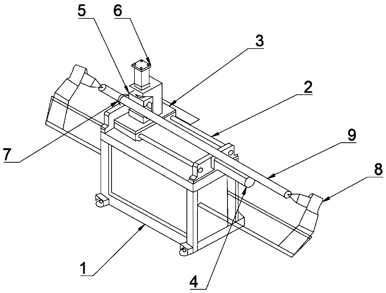
[0019] Embodiment 1: When using the leading small catheter clamping device of the present invention, pass the leading small catheter through the auxiliary positioning retaining ring, and set it between the double positioning apex, move the distance of the double positioning apex to fix the leading small catheter, set The mobile screw pair on the support frame drives the mobile platform to position and move on the slide rail. The external CNC host computer specifically controls the mobile screw pair. When the mobile platform drives the hydraulic jaws to move to the coordinates that need to be drilled, the hydraulic cylinder will make The hydraulic claw moves, and a circular cutter is arranged between the upper claw and the lower claw of the hydraulic claw, and the overflow hole is opened at each position with the rotation of the small leading pipe.

Embodiment 2

[0021] Using the advanced small catheter clamping device of the present invention, the double positioning tip can be improved into a single positioning tip, and one end of the advanced small catheter is provided with an advanced small catheter tip shrinking machine. The drilling process is carried out on the clamping device, and the characteristics of the rotation and forward movement of the screw rod are used to complete the rotation of the hydraulic claws at various positions of the leading small conduit, and to make the forming effect of the cone head of the leading small conduit better than the traditional processing technology. .

[0022] In addition, the terms "first" and "second" are used for descriptive purposes only, and cannot be interpreted as indicating or implying relative importance or implicitly specifying the quantity of indicated technical features. Thus, the features defined as "first" and "second" may explicitly or implicitly include one or more of these fea...


PUM


Abstract

The invention discloses a novel advanced small pipe clamping device which comprises a supporting frame, sliding rails, a moving platform, a moving screw rod pair, a hydraulic clamping claw, a hydraulic cylinder, an auxiliary positioning stop ring, double-positioning centres and an advanced small pipe. Foundation bolts are arranged at the four supporting corners of the supporting frame. The slidingrails are stainless steel I-shaped sliding rails and are arranged at the top end of the supporting frame. The moving platform is arranged on the sliding rails and is erected on the sliding rails through a sliding mechanism matched with the sliding rails. The moving screw rod pair is of a bidirectional telescopic structure in the linear direction and comprises a body end and a telescopic end, thebody end of the moving screw rod pair is fixedly installed on a supporting pillar of the supporting frame, and the telescopic end of the moving screw rod pair is fixedly connected with the bottom endof the moving platform. The novel advanced small pipe clamping device is simple and ingenious in structure and can be installed in combination with an existing sharp contracting machine, upgrading ismade effectively based on the existing sharp contracting machine, efficiency is high, prepared advanced small pipes are uniformed in shape and structure, exquisite in appearance and good in quality, and a large amount of labor and material resources are saved.

Description

technical field [0001] The invention relates to a mechanical clamping and positioning device, in particular to a novel advanced small catheter clamping device. Background technique [0002] At present, a large number of traditional production methods are still used for the processing and production of the advanced small catheter. It is divided into two major processes: front-end heating and hydraulic drilling. The two processes require two different machines, and the middle requires manpower to move the advanced small catheter. The corresponding processing stations are waiting for processing, with many process flows, slow processing speed, and high labor costs. Contents of the invention [0003] The technical problem to be solved by the present invention is to provide a novel advanced small catheter clamping device for the above problems. [0004] In order to solve the above technical problems, the technical solution provided by the present invention is: a new type of adv...

Claims


Application Information

Patent Timeline
Patent Type & Authority Applications(China)
IPC IPC(8): B23Q3/00
CPCB23Q3/00B23Q2703/10
Inventor 高静
Owner JIANGSU XINPENG ENERGY TECH
Why Eureka
Try Eureka