
An adjustable clamping device

A clamping device and adjustable technology, applied in the field of font bending machines, can solve the problems of affecting the cutting effect, clamping gap, inconvenient installation and disassembly, etc., and achieve the effect of easy promotion, easy clamping adjustment, and simple structure

Active Publication Date: 2020-04-28
潍坊达创数控设备有限公司
View PDF7 Cites 0 Cited by
  • Summary
  • Abstract
  • Description
  • Claims
  • Application Information

AI Technical Summary

Problems solved by technology

The traditional bending is made by hand, it is difficult to guarantee the quality of the encircling characters and the efficiency is low, so it is gradually replaced by the bending machine
The bending machine includes feeding device, bending device and milling device. The existing aluminum plate needs to be cut before bending to facilitate the subsequent bending. At present, there are still some problems in the bending machine. Some cutting and adjusting motion devices are complicated to assemble, and at the same time, it is inconvenient to install and disassemble the control
In the process of use, after changing materials of different heights and thicknesses, the adjustment process is time-consuming and laborious, and the stability is not high. When changing materials and making a deep adjustment, beginners need to adjust for about a day, and experienced masters also need 2 to adjust. -3 hours, the deviation of cutting depth is prone to occur; in addition, due to the different edge thicknesses of different types of aluminum plates, there may even be an aluminum plate with a thick edge and a thin edge, and clamping may occur when clamping such an aluminum plate The occurrence of gaps will affect the cutting effect and the bending effect

Method used


Image

  • An adjustable clamping device
  • An adjustable clamping device
  • An adjustable clamping device

Examples


Embodiment Construction

[0023] The technical solutions of the present invention will be described in detail below in conjunction with embodiments. The following examples are only used to illustrate the technical solutions of the present invention more clearly, and therefore are only examples, rather than limiting the protection scope of the present invention.

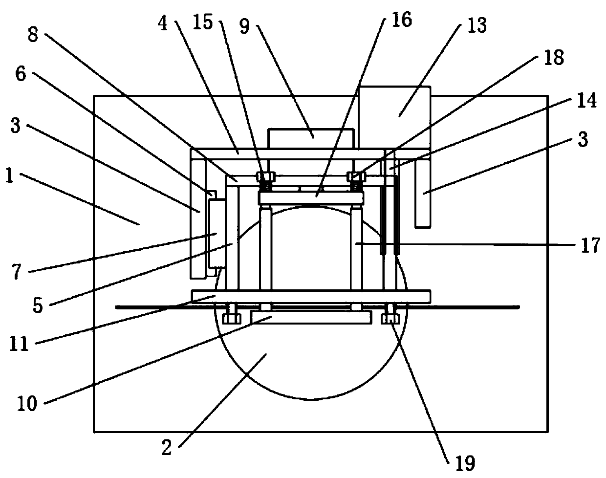
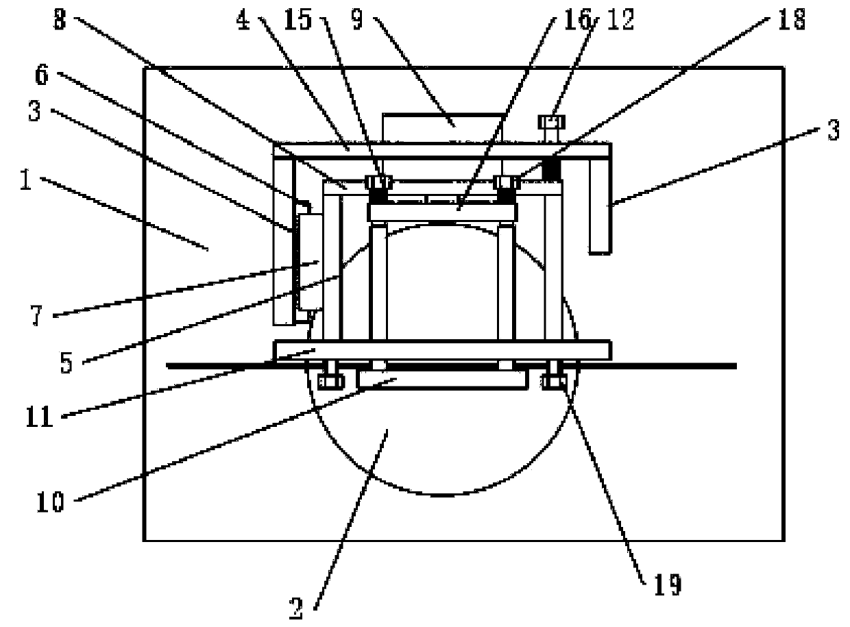
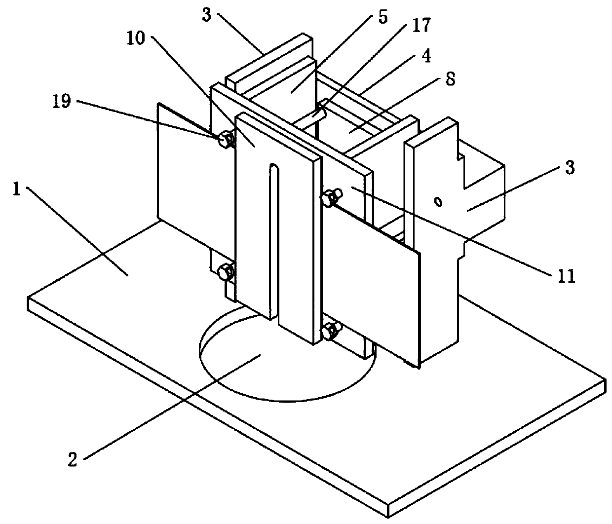
[0024] refer to Figure 1-Figure 4 As shown, the adjustable clamping device includes a workbench 1, and a through hole 2 for passing through the cutting knife is provided on the workbench 1, that is to say, the up and down movement of the cutting knife can cut the clamped aluminum plate, and the workbench 1 The main body fixing plate 3 arranged in parallel is arranged on the top, the inner end of the main body fixing plate 3 is provided with a fastening fixing plate 4, the outer end of the main body fixing plate 3 is open, and the connecting plate 5 is slidably installed between the main body fixing plates 3, The relative inner side of the fi...


PUM


Abstract

The invention provides an automatic adjusting and clamping device which comprises a workbench. A through hole for running through a cutter is formed in the workbench. Parallel body fixing plates are arranged on the workbench. A fastening fixing plate is arranged at the rear ends of the body fixing plates. The front ends of the fixing plates are open. Connecting plates are slidingly installed between the body fixing plates. The inner ends of the connecting plates are provided with a power fixing plate close to the fastening fixing plate. The outer ends of the connecting plates are provided witha clamping rear plate. A power part is arranged at the center of the power fixing plate. The power part is in power connection with a clamping front plate. The clamping front plate is located on theouter side of the clamping rear plate. A gap for clamping aluminum plates is formed between the clamping front plate and the clamping rear plate. An adjusting part for adjusting the distance between the power fixing plate and the fastening fixing plate is arranged on the fastening fixing plate. The automatic adjusting and clamping device has the technical advantages of being simple in structure, convenient to popularize, capable of conveniently clamping and adjusting the clamped aluminum plates, suitable for clamping different types of aluminum plates, and capable of providing a proper cuttingdepth for bending.

Description

technical field [0001] The invention relates to the technical field of font bending machines, in particular to an adjustable clamping device. Background technique [0002] Three-dimensional luminous characters are a common form of advertising for merchants. They have the advantages of beautiful and high-end appearance and low cost, so they have become the first choice for merchants in recent years. The main work of making the edge of three-dimensional luminous characters is to surround the edge, which mainly includes folding and bending. The traditional bending is made by hand, it is difficult to guarantee the quality of the encircling characters and the efficiency is low, so it is gradually replaced by the bending machine. The bending machine includes feeding device, bending device and milling device. The existing aluminum plate needs to be cut before bending to facilitate the subsequent bending. At present, there are still some problems in the bending machine. Some cutti...

Claims


Application Information

Patent Timeline
Patent Type & Authority Patents(China)
IPC IPC(8): B23Q3/06B23P23/04
CPCB23P23/04B23Q3/062
Inventor 李龙亭康瑞民
Owner 潍坊达创数控设备有限公司
Learn More