Motor machining and compacting device

A technology of pressing device and pressing plate, which is applied to metal processing equipment, grinding/polishing safety devices, manufacturing tools, etc., can solve the problem that the motor processing pressing device lacks heat dissipation measures, and the motor processing pressing device has a single structure and is disadvantageous. The problem of long-term use of the device can achieve the effect of simple and practical fixed structure, effective fixed function and reasonable design

Pending Publication Date: 2020-02-21
苏州博特蒙电机有限公司
View PDF0 Cites 0 Cited by
  • Summary
  • Abstract
  • Description
  • Claims
  • Application Information

AI Technical Summary

Problems solved by technology

[0003] When the existing motor processing and pressing devices are installed and used, first of all, some motor processing and pressing devices have a single structure and a single function, which is not conducive to people's use, and the motor is inconvenient to be fixed during the processing process, which reduces work efficiency and brings inconvenience to the staff. Bringing potential safety hazards, some motor processing and pressing devices lack heat dissipation measures, which is not conducive to the long-term use of the device

Method used


Image

  • Motor machining and compacting device
  • Motor machining and compacting device
  • Motor machining and compacting device

Examples


Embodiment Construction

[0031] In order to make the technical means, creative features, goals and effects achieved by the present invention easy to understand, the present invention will be further described below in conjunction with specific embodiments.

[0032] In the description of the present invention, it should be noted that the terms "upper", "lower", "inner", "outer", "front end", "rear end", "both ends", "one end", "another end" The orientation or positional relationship indicated by etc. is based on the orientation or positional relationship shown in the drawings, and is only for the convenience of describing the present invention and simplifying the description, rather than indicating or implying that the referred device or element must have a specific orientation, use a specific Azimuth configuration and operation, therefore, should not be construed as limiting the invention. In addition, the terms "first" and "second" are used for descriptive purposes only, and should not be understood ...


PUM


Abstract

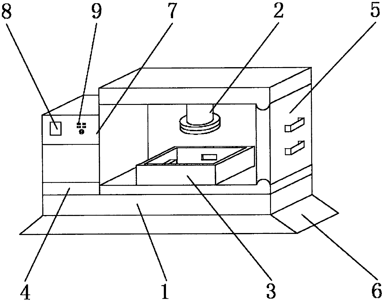
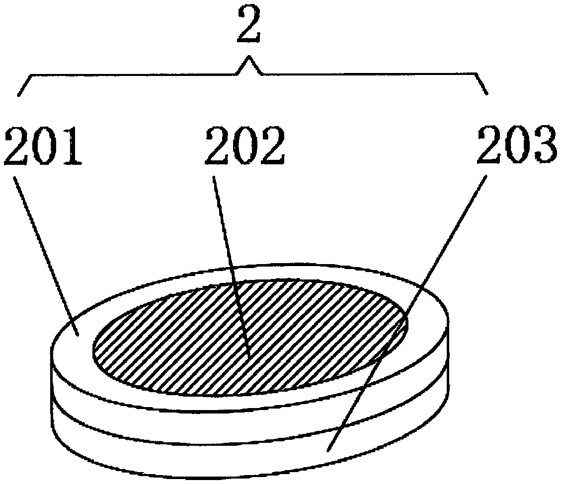
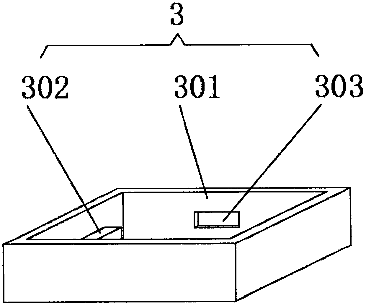
The invention discloses a motor machining and compacting device. The motor machining and compacting device includes a workbench main body, wherein a base is arranged on the outer surface at the lowerend of the workbench main body; a fixing mechanism is arranged on the inner surface at the lower end of the workbench main body; a multifunctional compacting mechanism is arranged on the inner surfaceat the upper end of the workbench main body; a push-pull visual mechanism is arranged on the inner surface on one side of the workbench main body; a heat dissipation mechanism is arranged on the outer surface at the upper end of the workbench main body; a controller is arranged on the outer surface at the upper end of the heat dissipation mechanism; a display screen and control buttons are arranged on the outer surface at the front end of the controller; and the control buttons are positioned on one side of the display screen. The motor machining and compacting device provided by the invention can provide multifunctional compaction and is convenient to fix during working and is capable of dissipating heat through the arranged multifunctional compacting mechanism, the fixing mechanism, theheat dissipation mechanism and the push-pull visual mechanism, and the invention further provides a visual push-pull plate.

Description

technical field [0001] The invention relates to the field of rotor processing, in particular to a motor processing and pressing device. Background technique [0002] Motor refers to an electromagnetic device that realizes the conversion or transmission of electrical energy according to the law of electromagnetic induction, or converts one form of electrical energy into another form of electrical energy. The motor converts electrical energy into mechanical energy, and the generator converts mechanical energy into Electric energy, its main function is to generate driving torque. As the power source of electrical appliances or various machinery, the current motor is easier to burn than in the past. Due to the continuous development of insulation technology, the design of the motor requires both increased output and It is required to reduce the volume, so that the thermal capacity of the new motor is getting smaller and smaller, and the overload capacity is getting weaker and we...

Claims


Application Information

Patent Timeline
Patent Type & Authority Applications(China)
IPC IPC(8): B24B19/00B24B41/00B24B41/06B24B55/00B24B55/02
CPCB24B19/00B24B41/00B24B41/06B24B55/00B24B55/02
Inventor 朱利青吴志民周华平顾建新
Owner 苏州博特蒙电机有限公司
Why Eureka
Try Eureka