Cutting device and cutting method for composite steel plate processing

A composite steel plate and cutting device technology, which is applied in the field of steel processing, can solve problems affecting composite steel plates, reduce efficiency, and be easily corroded, and achieve the effect of utilizing the surface area and reducing the moving range

Active Publication Date: 2021-01-08
HUAIBEI HUABO MACHINERY MFG
View PDF13 Cites 2 Cited by
  • Summary
  • Abstract
  • Description
  • Claims
  • Application Information

AI Technical Summary

Problems solved by technology

[0003] In the cutting process of the steel plate, in the prior art, in order to ensure the cutting effect, the position of the steel plate needs to be fixed, so when the steel plate is cut and processed to form multiple small steel plates, it is necessary to move the cutting knife in a large range or to The position of the steel plate is moved and re-fixed. The former requires a large-area processing platform and equipment sufficient to support the large-area movement of the cutting knife. The latter requires a lot of time for repeated positioning, which reduces the production efficiency. , when cutting to the connection surface between layers, it is easy to delaminate between the layers of the composite steel plate due to the loose connection, and the gap at the layered place is easy to corrode, which affects the effective service life of the composite steel plate. How to improve the cutting of the composite steel plate efficiency, and reduce the phenomenon of cutting and delamination between the layers of the composite steel plate, and improve the effective service life of the composite steel plate. In order to solve this problem, the present invention provides the following solutions

Method used


Image

  • Cutting device and cutting method for composite steel plate processing
  • Cutting device and cutting method for composite steel plate processing
  • Cutting device and cutting method for composite steel plate processing

Examples


Embodiment Construction

[0036] The technical solutions in the embodiments of the present invention will be clearly and completely described below. Obviously, the described embodiments are only some of the embodiments of the present invention, but not all of them. Based on the embodiments of the present invention, all other embodiments obtained by persons of ordinary skill in the art without creative efforts fall within the protection scope of the present invention.

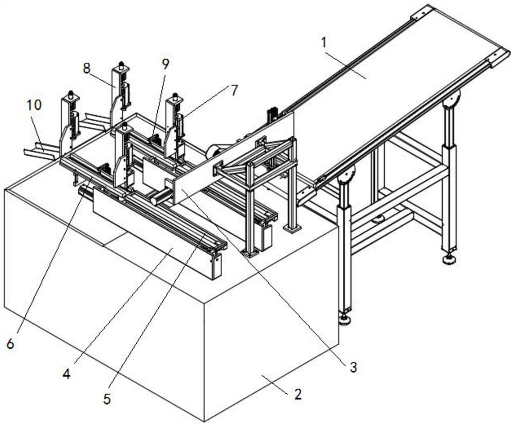
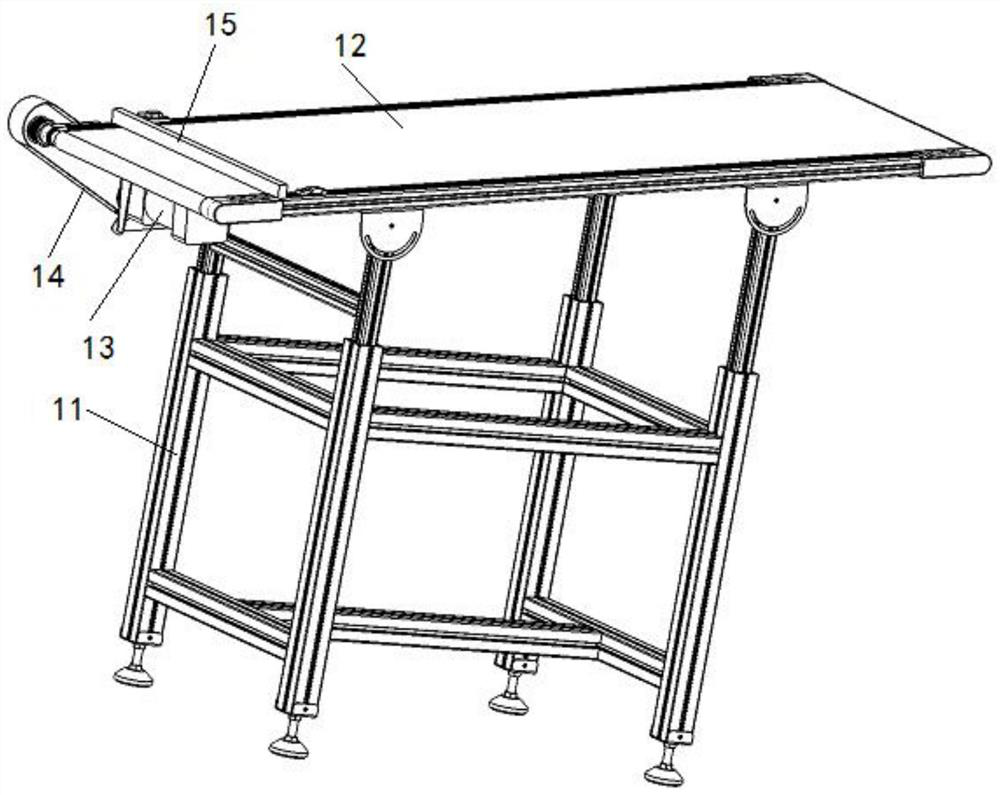
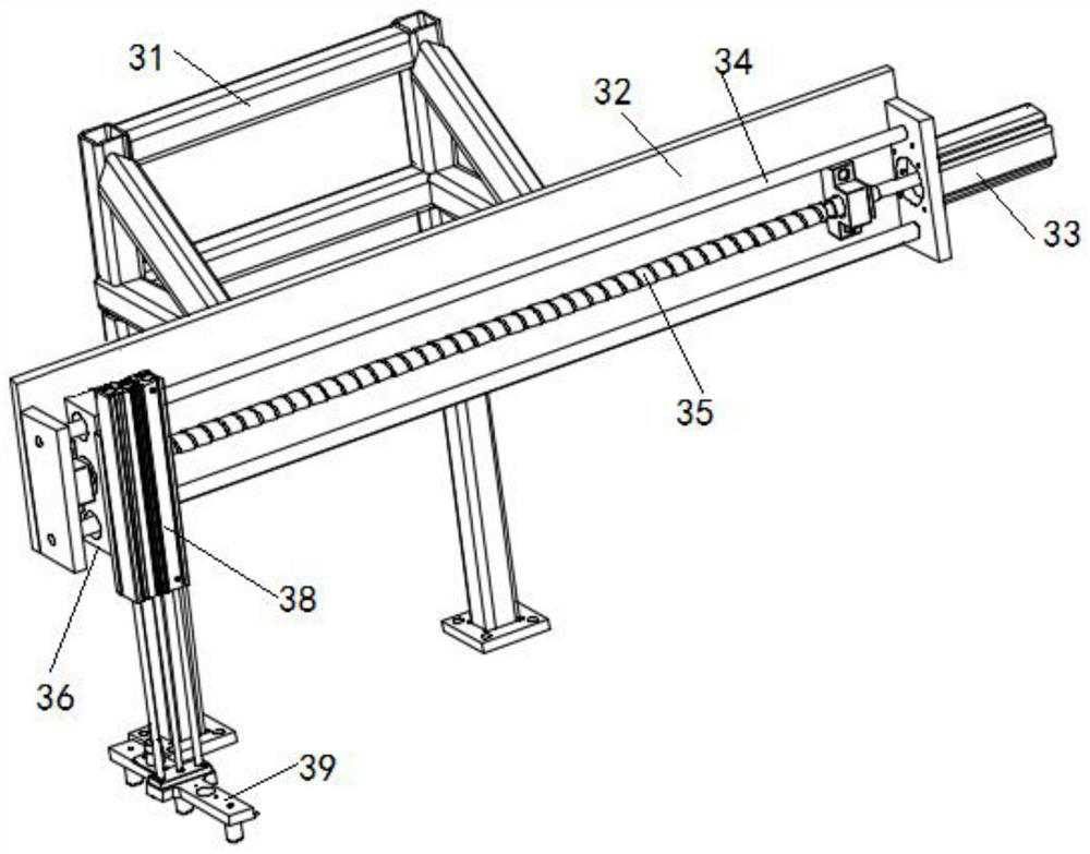
[0037] A cutting device for composite steel plate processing, such as Figure 1-Figure 7 As shown, it includes a feeding device 1 and a processing platform 2. The feeding device transfers the composite steel plate to be cut close to the processing platform 2. A material transfer device 3, a translation device 4, and a material clamping device are fixedly installed on the processing platform 2. Device 5, feeding track 6, pressing device 9 and finished material feeding port 10, there is a gap between the material clamping device 5 and the ...


PUM


Abstract

The invention discloses a cutting device for composite steel plate machining and a cutting method of the cutting device. The cutting device comprises a feeding device and a machining platform. A material transfer device, translation devices, material clamping devices, conveying rails, pressing devices and finished material feeding openings are fixedly mounted on the machining platform. Gaps are reserved between the material clamping devices and the conveying rails, water cutting knives are arranged above the gaps, and gas spray heads are arranged above the positions, close to one ends of the finished material feeding openings, of the conveying rails. According to the cutting device, a composite steel plate is subjected to translation through the translation devices, the composite steel plate does not need to be located many times, the cutting distance of the water cutting knives in the horizontal direction is normally slightly larger than the width of the machined composite steel plate, and therefore the moving range of the water cutting knives is greatly narrowed, and the superficial area of the machining platform is effectively utilized; and by means of the cutting method, the situation that a steel plate on the bottommost layer and adjacent layers and other layers bear pressure to be separated can be avoided, and cutting quality is improved.

Description

technical field [0001] The invention belongs to the technical field of steel processing, and in particular relates to a cutting device for processing composite steel plates and a cutting method thereof. Background technique [0002] Clad steel plate is a kind of steel plate made by combining single or multiple steel plates, so that the clad steel plate has the characteristics of two or more steel plates, thereby improving the properties and application range of the clad steel plate. In the actual production process, in order to make the steel plate can Applicable to a variety of environments, it is necessary to cut the composite steel plate into a specific shape. [0003] In the cutting process of the steel plate, in the prior art, in order to ensure the cutting effect, the position of the steel plate needs to be fixed, so when the steel plate is cut and processed to form multiple small steel plates, it is necessary to move the cutting knife in a large range or to The posit...

Claims


Application Information

Patent Timeline
Patent Type & Authority Patents(China)
IPC IPC(8): B24C1/04B24C3/00
CPCB24C1/045B24C3/00
Inventor 谭崴
Owner HUAIBEI HUABO MACHINERY MFG
Why Eureka
Try Eureka