High-precision and wear-resisting trim strip for automobile gear lever handle
A high-precision, wear-resistant strip technology, which is applied in the direction of vehicle components, upper structure, upper structure sub-assembly, etc., can solve the problems of easy falling off of gear armrest trim strips, short service life, poor wear resistance, etc., to achieve anti-slip Good grinding performance, long service life, convenient and firm installation
- Summary
- Abstract
- Description
- Claims
- Application Information
AI Technical Summary
Problems solved by technology
Method used
Image
Examples
Embodiment 1
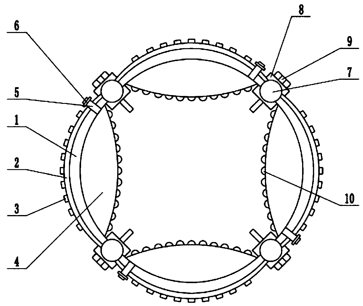
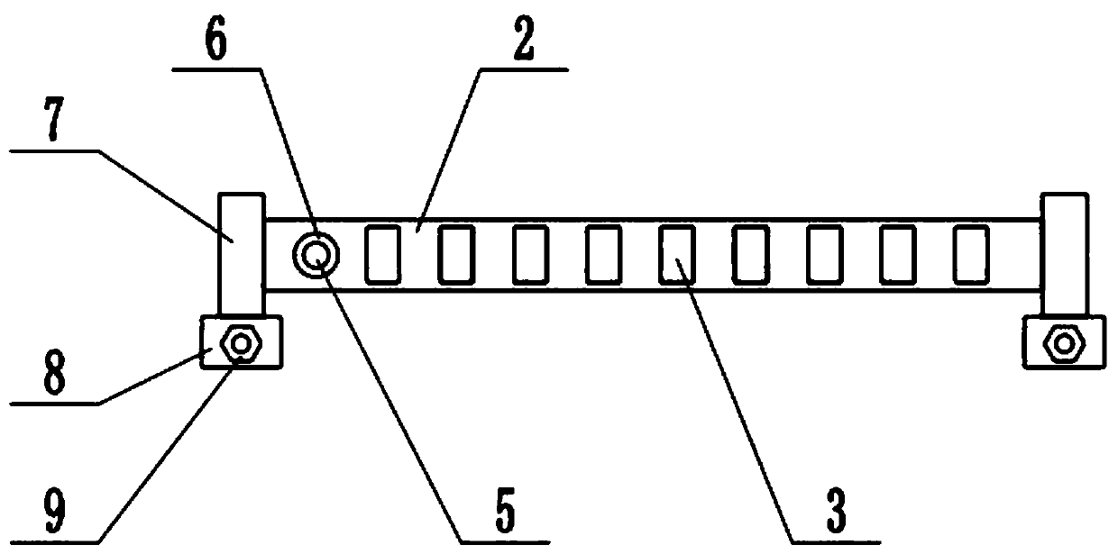
[0021] see Figure 1-3 , in an embodiment of the present invention, a high-precision wear-resistant car gear armrest trim, including a support bar 1 and a wear-resistant bar 2, there are four support bars 1, and two support bars 1 are hinged together by a rotating shaft 7 , the lower end of the rotating shaft 7 is fixedly connected with the installation block 8, the installation block 8 is penetrated with a screw 9, the screw 9 is threaded with the installation block 8, and the four support bars 1 are connected end to end to form a ring, which is set on the gear armrest and tightened Screw 9, so that the tail of the screw 9 is screwed into the gear armrest, and the installation block 8 is firmly fixed on the gear armrest with the screw 9, so that the device remains stable, and the outer wall of the support bar 1 is fixedly connected with a wear-resistant strip 2 , the wear-resistant strip 2 is made of wear-resistant copper alloy, and there are convex ribs 3 distributed on the ...
Embodiment 2
[0023] In the embodiment of the present invention, a high-precision wear-resistant automobile gear armrest trim strip includes a support strip 1, a wear-resistant strip 2 and an airbag 4. There are four support strips 1 in total, and two support strips 1 are hinged by rotating shafts 7 Together, the lower end of the rotating shaft 7 is fixedly connected with the installation block 8, the installation block 8 is penetrated with a screw 9, the screw 9 is threaded with the installation block 8, and the four support bars 1 are connected end to end to form a ring, which is sleeved on the gear armrest. Tighten the screw 9, so that the tail of the screw 9 is screwed into the gear armrest, and the installation block 8 is firmly fixed on the gear armrest with the screw 9, so that the device remains stable, and the outer wall of the support bar 1 is fixedly connected with a wear-resistant Strip 2, wear-resistant strip 2 is made of wear-resistant copper alloy, and convex ribs 3 are distri...
Embodiment 1、 Embodiment 2
[0024] In combination with Embodiment 1 and Embodiment 2, the working principle of the present invention is: put the device on the gear handrail, tighten the screw 9, screw the tail of the screw 9 into the gear handrail, and use the screw 9 to install the mounting block 8 It is firmly fixed on the gear armrest to keep the device stable. The wear-resistant strip 2 is made of wear-resistant copper alloy. There are convex ribs 3 distributed on the wear-resistant strip 2. The convex ribs 3 and the wear-resistant strip 2 are integrally formed, increasing the The frictional force makes the palm of the driver more fit with the gear armrest, improves the grip comfort, opens the valve 6, and inflates the airbag 4 through the intake pipe 5, so that the airbag 4 is inflated, and the side wall of the airbag 4 is in contact with the barrier. The gear armrests are closely fitted, filling the gap between the support bar 1 and the gear armrest, making the contact between the support bar 1 and ...
PUM
 Abstract
Description
Claims
Application Information
 - R&D
- Intellectual Property
- Life Sciences
- Materials
- Tech Scout
- Unparalleled Data Quality
- Higher Quality Content
- 60% Fewer Hallucinations
Browse by: Latest US Patents, China's latest patents, Technical Efficacy Thesaurus, Application Domain, Technology Topic, Popular Technical Reports.
© 2025 PatSnap. All rights reserved.Legal|Privacy policy|Modern Slavery Act Transparency Statement|Sitemap|About US| Contact US: help@patsnap.com


