Supercharge Your Innovation With Domain-Expert AI Agents!

Conceal zipper tape pressing and shaping device

A technology of invisible zipper and chain belt, which is applied in the direction of heating/cooling fabrics, textiles and papermaking, and fabric surface trimming, etc. It can solve the problems that zipper chain belts are prone to wrinkles, inconvenient to process and use, and reduce the appearance of products, so as to improve the state of wrinkles , Improve flatness, improve production efficiency

Inactive Publication Date: 2020-02-21
义乌市鸿盛拉链有限公司
View PDF0 Cites 0 Cited by
  • Summary
  • Abstract
  • Description
  • Claims
  • Application Information

AI Technical Summary

Problems solved by technology

[0003] The teeth of the invisible zipper and the chain belts connected on both sides are usually connected together by sewing machine. The zipper belt after sewing is easy to wrinkle, which not only reduces the beauty of the product, but also is not convenient for subsequent processing. use

Method used


Image

  • Conceal zipper tape pressing and shaping device
  • Conceal zipper tape pressing and shaping device
  • Conceal zipper tape pressing and shaping device

Examples


Embodiment 1

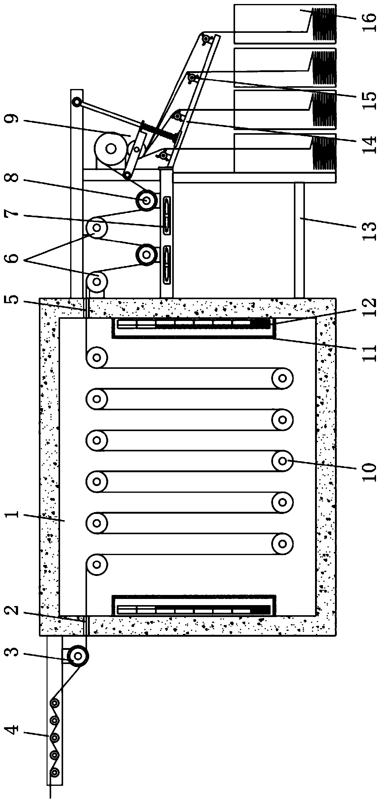
[0035] Embodiment one, with reference to Figure 1-2 , a kind of hidden zipper chain belt ironing and shaping device, comprising a heating box 1 and a frame body 13, a transition frame 4 is installed on one side of the heating box 1, and a feed guide roller 3 is provided on one side of the bottom surface of the transition frame 4, and the feed guide One side of the roller 3 is located on the side wall of the heating box 1 and is provided with a feed port 2, and the opposite side of the feed port 2 is provided with a discharge port 5, and the other side of the heating box 1 is equipped with a frame body 13, and the top of the frame body 13 is provided with a There is a turning roller 6, a ceramic heater 12 and an unpowered roller 10 are arranged inside the heating box 1, a discharge guide roller 8 is arranged under the turn roller 6, and a plurality of cooling fans 7 are arranged below the discharge guide roller 8, and the frame body 13 One side is respectively equipped with a ...

Embodiment 2

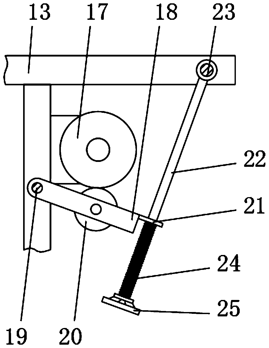
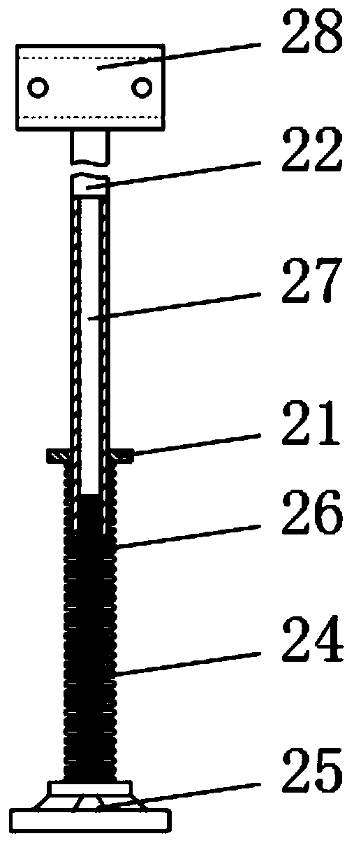
[0036] Embodiment two, refer to Figure 2-4 One end of the turret 18 that fixes the pressure wheel 20 in the flattening adjustment mechanism 9 is connected with the fixed frame through the rotating shaft 19, and the other end is fixedly connected with the connecting shaft 23 erected on the frame body 13 through the limiting piece 21 and the connecting rod 22, The inner lower end of the connecting rod 22 is processed with a threaded hole 27, and the lower end of the connecting rod 22 is threadedly connected with the threaded rod 26 provided with the spring 24 through the threaded hole 27. The upper end of the connecting rod 22 is welded with a connecting sleeve 28, and the connecting sleeve 28 is processed with Stopper screw hole, handwheel 25 is installed on the lower end of the threaded pipe, polyurethane layer is provided on the surface of pressure roller 20, and it is in contact with receiving roller 17, there are multiple pressure rollers 20, and multiple pressure rollers 2...

Embodiment 3

[0037] Embodiment three, refer to figure 1 with Image 6, the material distribution frame 14 is obliquely connected to the side surface of the frame body 13, and a plurality of material distribution rollers 15 are installed on the inclined surface of the material distribution frame 14, and each material distribution roller 15 is provided with a plurality of three rectangular feeding Plate 31, sprocket wheel 32 is installed on one end of each distribution roller 15, and is connected with distribution motor 34 by chain 33 transmission, drives a plurality of distribution rollers 15 to rotate simultaneously by distribution motor 34, utilizes distribution roller 15 The beating plate 31 of the invisible zipper is pushed aside to realize the large swing of the invisible zipper, so that the invisible zipper after flattening and shaping can be arranged in the storage box 16 in an orderly manner.


PUM


Abstract

The invention discloses a conceal zipper tape pressing and shaping device, which comprises a heating chamber and a frame. A transition frame is mounted on one side of the heating chamber, a feeding guide roller is arranged on one side of the bottom surface of the transition frame, the side wall of the heating chamber is provided with a feeding port on one side of the feeding guide roller, and a discharging port faces the feeding port. To-be-smoothened conceal zippers pass through the transition frame and the feeding guide roller and sequentially bypass an unpowered drum, turning rollers, discharging guide rollers and a pressing mechanism, and the conceal zippers wound on the unpowered drum are heated for shaping through ceramic heaters arranged in the heating chamber to improve a wrinkle state of zipper tapes. A plurality of cooling fans are mounted under the discharging guide rollers and blow to cool the ironed zipper tapes to avoid secondary creasing of the zipper tapes accumulated in a collection box, the cooled zipper tapes enter the pressing adjustment mechanism, the zipper tapes wound on a supporting roller are extruded through pressing wheels, and accordingly smoothness of the zipper tapes is further improved.

Description

technical field [0001] The invention relates to the technical field of invisible zipper processing equipment, in particular to an ironing and setting device for invisible zipper chain belts. Background technique [0002] The invisible zipper is composed of chain teeth, sliders, limit codes (front code and rear code) or locking parts. Among them, the chain teeth are the key part, which directly determines the side pull strength of the zipper. Generally, the invisible zipper has two chain belts, and each chain belt has a row of chain teeth, and the two rows of chain teeth are arranged alternately. [0003] The teeth of the invisible zipper and the chain belts connected on both sides are usually connected together by sewing machine. The zipper belt after sewing is easy to wrinkle, which not only reduces the beauty of the product, but also is not convenient for subsequent processing. use. [0004] For this reason, an invisible zipper string ironing and shaping device is propo...

Claims


Application Information

Patent Timeline
Patent Type & Authority Applications(China)
IPC IPC(8): D06C7/02D06C15/00
CPCD06C7/02D06C15/00
Inventor 陈一箭任大龙王起
Owner 义乌市鸿盛拉链有限公司
Features
  • R&D
  • Intellectual Property
  • Life Sciences
  • Materials
  • Tech Scout
  • Unparalleled Data Quality
  • Higher Quality Content
  • 60% Fewer Hallucinations
Learn More