
Textile fabric guiding device

A material guiding device and technology for textile fabrics, which are applied in textiles and papermaking, fabric surface trimming, thin material processing, etc., can solve the problems of affecting processing, uneven processing of fabrics, secondary folds of textiles, etc., to promote flow, facilitate internal and external The exchange of air flow, the effect of increasing the friction area

Inactive Publication Date: 2021-11-05
杨春
View PDF0 Cites 0 Cited by
  • Summary
  • Abstract
  • Description
  • Claims
  • Application Information

AI Technical Summary

Problems solved by technology

[0005] Aiming at the deficiencies of the prior art, the present invention provides a textile fabric guide device, which solves the problem that the existing textile fabric guide device does not smooth the fabric during use, and the guide member and the textile contact each other, causing the textile fabric to Secondary wrinkles, problems that affect subsequent processing

Method used


Image

  • Textile fabric guiding device
  • Textile fabric guiding device
  • Textile fabric guiding device

Examples


Embodiment 1

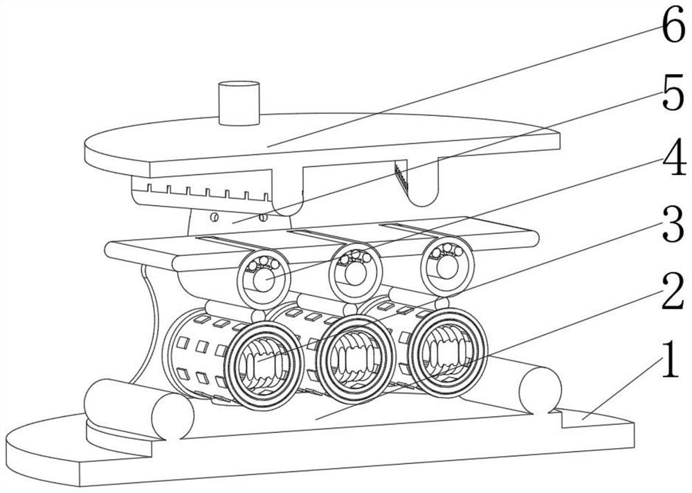
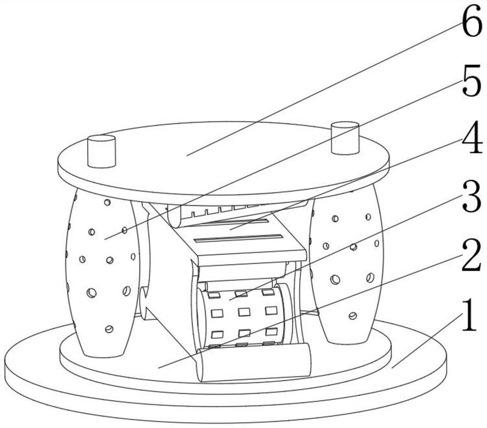
[0041] see Figure 1-6 , the present invention provides a technical solution: a textile material guide device, specifically comprising:

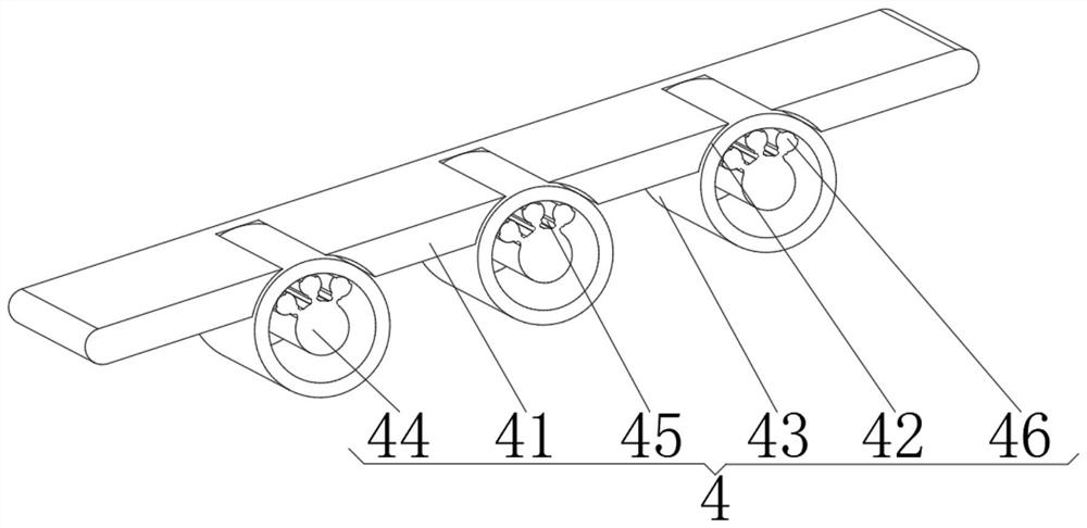
[0042] Seat plate 1, the seat plate 1 has a circular plate body, a disc seat 2 installed on the top of the circular plate body, a heating device 3 installed on the top of the disc seat 2, and a heating device 3 installed on the top The material guide plate 4, and the support device 5 installed on the top of the circular plate body and positioned at the front and back of the disc seat 2, and the flat pressing device 6 installed on the top of the support device 5, the material guide plate 4 includes:

[0043]The fabric panel 41, the fabric panel 41 has a strip-shaped plate body, and a through hole 42 provided at the bottom of the strip-shaped plate body, and the abutment cylinder 43 arranged in the inner cavity of the through hole 42, and the inner cavity of the abutment cylinder 43 The positioning shaft post 44 in the middle position, the el...

Embodiment 2

[0053] see Figure 1-6 On the basis of Embodiment 1, the present invention provides a technical solution: a textile material guiding method, comprising the following steps,

[0054] Step 1: placing the textile on the fabric panel 41 and contacting with the top of the outer surface of the abutment cylinder 43;

[0055] Step 2: Continuously drag the textile along the fabric plate 41, so that it moves along the fabric plate 41, and use the friction force to rotate the abutment wheel 43;

[0056] Step 3: The rotation of the contact wheel 43 drives the rubber sleeve 33 and the magnetic block drum 34 to rotate, the position of the magnetic field line is changed through the rotation of the magnetic block drum 34, and the electromagnetic conversion power generation is performed by the generator coil 36, and the iron The columns 35 cooperate with each other to generate magnetic force, and at the same time, the generator coil 36 supplies electric energy to the heating plate 32 to gener...


PUM


Abstract

The invention discloses a textile fabric guiding device. The device specifically comprises a seat plate, a thermalization device installed at the top of a disc seat, a guiding plate installed at the top of the thermalization device and a flat pressing device installed at the top of a supporting device; and the guiding plate comprises a fabric plate, a through hole formed in the bottom of a strip-shaped plate body, an wheel abutting cylinder arranged in an inner cavity of the through hole, a positioning shaft column arranged in the middle of the inner cavity of the wheel abutting cylinder, an ejection rod installed on the top of the outer surface of the positioning shaft column, and a driven column installed on the top of the ejection rod. The invention relates to the technical field of textiles. Through the arrangement of the ejection rod, the wheel abutting cylinder is supported and fixed, so that the height of the top of the outer surface of the wheel abutting cylinder is increased, the contact area between the wheel abutting cylinder and a textile is increased, the textile is supported, and fibers are expanded; and wrinkles of the textile are removed, meanwhile, friction force generated by the textile is fully converted, so that energy is charged for other components in the device.

Description

technical field [0001] The invention relates to the technical field of textiles, in particular to a textile material guiding device. Background technique [0002] For many people in the textile industry, they may only know that it is used to weave cloth and make clothes for people to wear. Therefore, the raw material of clothes is the production of cloth through weaving and post-processing. In textile factories, it is usually produced The cloth is stored on the cloth rack for later processing. During use, the fabric is not smoothed, and the material guide member and the textile are in contact with each other, resulting in secondary wrinkles of the textile and affecting subsequent processing. [0003] The existing textile material guide device does not smooth the fabric during use, and the material guide member and the textile contact each other, resulting in secondary wrinkles of the textile and affecting subsequent processing. Contents of the invention [0004] (1) Solv...

Claims


Application Information

Patent Timeline
Patent Type & Authority Applications(China)
IPC IPC(8): D06C15/00B65H20/02B65H23/34B65H23/16
Inventor 杨春
Owner 杨春
Learn More