
Plate glass quality detection method based on laser continuous wave modulation principle

A quality inspection method and flat glass technology, applied in the direction of optical testing flaws/defects, measuring devices, optical devices, etc., can solve problems such as scratches on the flat glass surface, large errors, and wear of sensor probes

Active Publication Date: 2020-02-21
江苏飞天玻璃实业有限公司
View PDF6 Cites 3 Cited by
  • Summary
  • Abstract
  • Description
  • Claims
  • Application Information

AI Technical Summary

Problems solved by technology

[0002] The thickness of flat glass is a very important quality indicator in the production process of flat glass. Many plates have high requirements on the flatness, thickness and existence of defects on the plate surface. The disadvantage of measuring tools such as thickness gauges is that there is relative sliding between the flat glass and the measuring tool, which can easily cause scratches on the surface of the flat glass, and requires manual readings, resulting in large errors
In addition, the sensor probe of the contact thickness gauge also has a certain degree of wear and tear, and needs to be recalibrated frequently and the probe should be replaced regularly
For large-sized plates, laser triangulation and interferometry can be used to achieve non-contact measurement, but the actual measurement process is affected by various factors, such as jitter, so that the measurement accuracy will still be greatly affected

Method used


Image

  • Plate glass quality detection method based on laser continuous wave modulation principle
  • Plate glass quality detection method based on laser continuous wave modulation principle
  • Plate glass quality detection method based on laser continuous wave modulation principle

Examples


Embodiment Construction

[0060] Embodiments of the present invention are described in detail below, examples of which are shown in the drawings, wherein the same or similar reference numerals designate the same or similar elements or elements having the same or similar functions throughout. The embodiments described below by referring to the figures are exemplary and are intended to explain the present invention and should not be construed as limiting the present invention.

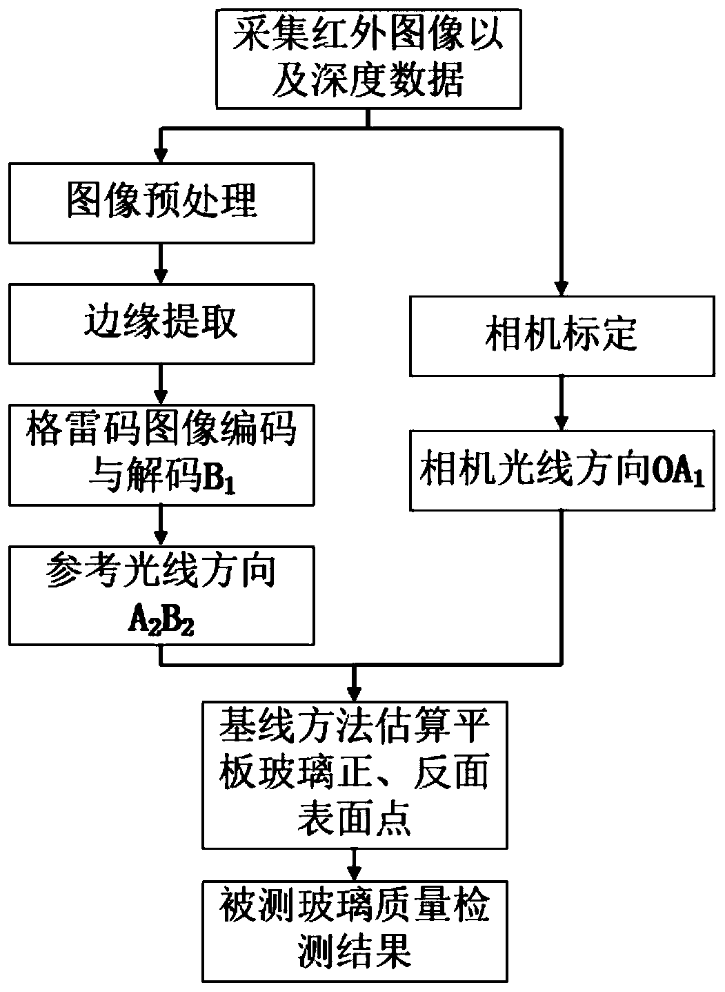
[0061] The flat glass quality detection method based on the laser continuous wave modulation principle of the present invention includes an image acquisition module, image preprocessing, edge extraction, Gray code image encoding and decoding, and a baseline method for estimating the front and back surface points of the flat glass;

[0062] The step 1 is used to collect infrared images and depth data by the image acquisition module using the depth camera and store them in the computer, and the external image includes the gray code ...


PUM


Abstract

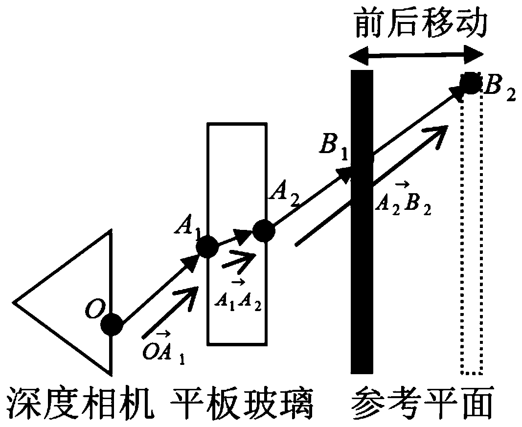
The invention discloses a plate glass quality detection method based on a laser continuous wave modulation principle. The plate glass quality detection method comprises the steps of image acquisition,image preprocessing, edge extraction, Gray code image encoding and decoding, and estimation of front and back surface points of plate glass by adopting a baseline method. The plate glass quality detection method is implemented by the steps of: acquiring an infrared image and depth data; preprocessing an acquired image; extracting edges of measured plate glass; encoding and decoding a Gray code image to obtain a front surface point of the detected plate glass and a reference light direction; calibrating a camera to obtain a light direction of the camera; and estimating a certain group of points corresponding to the front and back surfaces of the plate glass according to the baseline method so as to obtain a measurement result of the thickness of the plate glass, and respectively estimatingall points on the front and back surfaces simultaneously to obtain a three-dimensional shapes of the front and back surfaces of the plate glass, thereby being capable of measuring the defects and defect sizes of the front and back surfaces respectively. According to the plate glass quality detection method, the results of plate glass thickness measurement and defect size can be more precise.

Description

technical field [0001] The invention belongs to the field of product quality detection, and in particular relates to a flat glass quality detection method based on the principle of laser continuous wave modulation. Background technique [0002] The thickness of flat glass is a very important quality indicator in the production process of flat glass. Many plates have high requirements on the flatness, thickness and existence of defects on the plate surface. The shortcomings of measuring tools such as thickness gauges are that there is relative sliding between the flat glass and the measuring tool, which may easily cause scratches on the surface of the flat glass, and manual reading is required, resulting in large errors. In addition, the sensor probe of the contact thickness gauge is also subject to wear and tear, requiring frequent recalibration and regular replacement of the probe. For large-sized plates, laser triangulation and interferometry can be used to achieve non-co...

Claims


Application Information

Patent Timeline
Patent Type & Authority Applications(China)
IPC IPC(8): G01B11/06G01N21/88
CPCG01B11/06G01N21/8851G01N2021/8887
Inventor 顾君兰邹荣许桢英王匀
Owner 江苏飞天玻璃实业有限公司
Learn More