Slot pattern generation method and charging medium manufacturing method for suppressing eddy current effect
What is AI technical title?
AI technical title is built by PatSnap AI team. It summarizes the technical point description of the patent document.
A pattern generation and eddy current effect technology, applied in the field of electromagnetic field, to reduce eddy current loss, suppress eddy current effect, and improve energy transmission efficiency
Active Publication Date: 2021-12-17
BEIJING PINS MEDICAL
View PDF9 Cites 0 Cited by
Summary
Abstract
Description
Claims
Application Information
AI Technical Summary
This helps you quickly interpret patents by identifying the three key elements:
Problems solved by technology
Method used
Benefits of technology
Problems solved by technology
[0004] The purpose of the present invention is to provide a method for generating a groove pattern that suppresses the eddy current effect, so as to solve the technical problem of the irregularly shaped conductive plate groove pattern in the prior art
Method used
Image
Click on the blue label to locate the original text in one second.
Reading with bidirectional positioning of images and text.
Examples
Embodiment 1
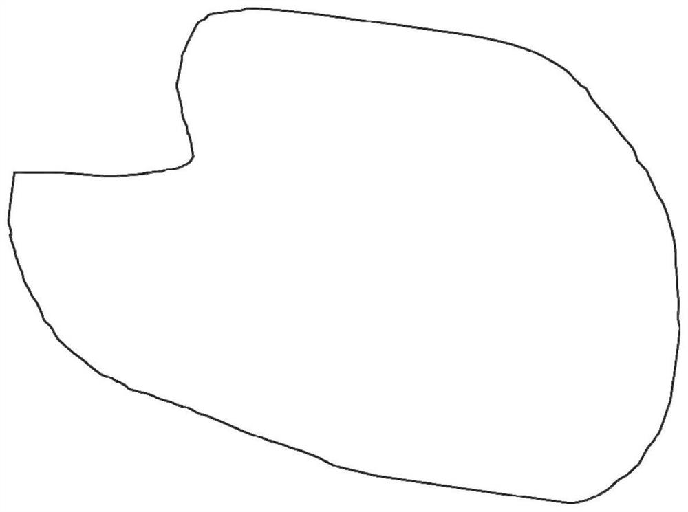
[0067] against figure 1 For the irregularly shaped metal plate shown, the method for generating a grooving pattern that suppresses the eddy current effect provided in this embodiment includes the following operation process:
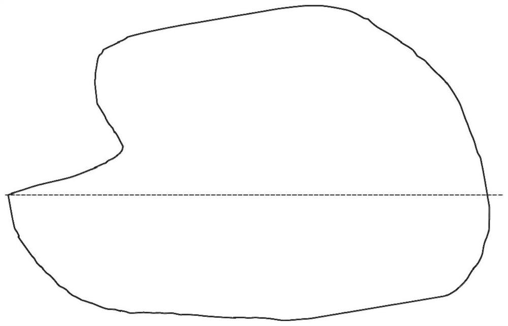
[0068] (1) For irregular shapes (such as figure 1 As shown), select the baseline with the longest shape of the metal plate, and rotate the shape of the metal plate to adjust the baseline to be horizontal (such as figure 2 );
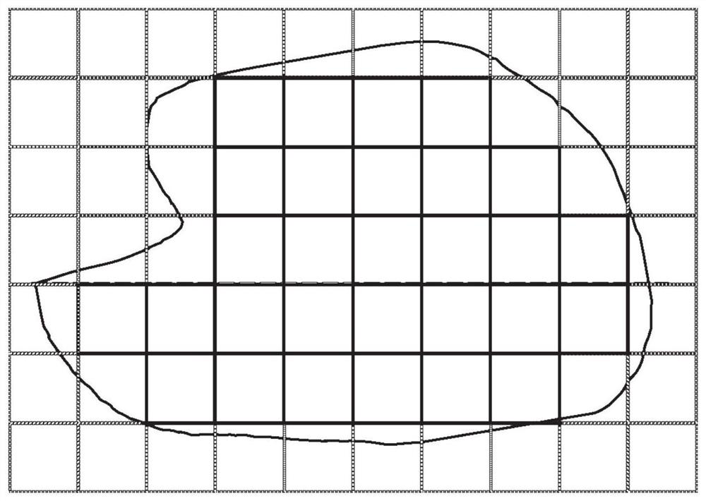
[0069] (2) The shape of the metal plate is divided into a plurality of small square grid units ( image 3 The solid line part in the outline).
[0070] (3) Based on the square grid unit, construct a fractal pattern in the square grid unit, such as Figure 4 The rice-shaped fractal pattern shown in the figure can also be used with other fractal patterns, such as the second-order Hilbert fractal pattern ( Figure 5 ).
[0071] (4) Connect the fractal patterns in each square grid unit sequentially (such as Figure 6-7 ), formi...
Embodiment 2
[0073] For metal plates with triangular shapes, such as Figure 10 and Figure 11 As shown, the method for generating a groove pattern that suppresses the eddy current effect provided in this embodiment includes the following operation process:
[0074] (1) For a triangular metal plate, take one side of the triangle as a benchmark, and rotate the shape of the metal plate to adjust the baseline to be horizontal;
[0075] (2) According to said benchmark, divide one layer of grid cells, then divide the second layer of network cells with the upper boundary of this layer of grid cells as a benchmark;
[0076] And so on... until the grid is covered;
[0077] (3) Build fractal patterns in each grid, such as Figure 4 The rice-shaped fractal pattern shown can also be selected from other fractal patterns, such as the 2nd-order Hilbert fractal pattern ( Figure 5 );
[0078] (4) Connect the fractal patterns in each square grid unit sequentially to form the grooving pattern of the e...
PUM
Abstract
The invention relates to the technical field related to electromagnetic fields, in particular to a method for generating a slot pattern and a method for manufacturing a charging medium for suppressing eddy current effects. The generation method of the slotting pattern for suppressing the eddy current effect comprises: S1. selecting a baseline on a conductive plate with an irregular shape, and the baseline is a line connecting two points on the boundary line of the conductive plate; S2. taking the baseline as Alignment, dividing the conductive plate into grids; S3. Constructing a fractal pattern in each grid to form a slotting pattern of the entire conductive plate. The present invention solves the boundary problem of the conductive plate with irregular shapes by selecting the baseline on the conductive plate and dividing the conductive plate into grids based on the baseline, and generates a fractal pattern for each grid by constructing a fractal pattern The groove pattern of the conductive plate with complex and irregular shapes reduces eddy current loss and improves energy transmission efficiency.
Description
technical field [0001] The invention relates to the technical field related to electromagnetic fields, in particular to a method for generating a slot pattern and a method for manufacturing a charging medium for suppressing eddy current effects. Background technique [0002] Wireless charging / power supply technology is applied in many fields, especially in mobile consumer electronics products and active implantable medical devices, and is usually based on the principle of electromagnetic coupling to charge / power products through electromagnetic induction. However, in the process of wireless charging / power supply based on the principle of electromagnetic coupling, there are conductive parts in the nearby environment that are heated due to eddy current effects, such as metal parts or soft magnetic material plates, etc. Particularly desirable to avoid in medical equipment, heating caused by eddy currents not only consumes electrical energy, reduces energy transfer efficiency bu...
Claims
Application Information
Patent Timeline
Application Date:The date an application was filed.
Publication Date:The date a patent or application was officially published.
First Publication Date:The earliest publication date of a patent with the same application number.
Issue Date:Publication date of the patent grant document.
PCT Entry Date:The Entry date of PCT National Phase.
Estimated Expiry Date:The statutory expiry date of a patent right according to the Patent Law, and it is the longest term of protection that the patent right can achieve without the termination of the patent right due to other reasons(Term extension factor has been taken into account ).
Invalid Date:Actual expiry date is based on effective date or publication date of legal transaction data of invalid patent.

