Figure filler structure inserted about inductor

A filler and inductor technology, which is applied in the field of graphic filler structure, can solve the problems of reducing the quality factor of inductors, increasing the energy loss of inductors, and achieving the effects of meeting density requirements, increasing qualityfactor, and reducing eddy current effects

Inactive Publication Date: 2011-06-01
SEMICON MFG INT (SHANGHAI) CORP +1
View PDF2 Cites 4 Cited by
  • Summary
  • Abstract
  • Description
  • Claims
  • Application Information

AI Technical Summary

Problems solved by technology

With the addition of the pattern filling structure, the eddy current effect (eddy current effect) is introduced, that is, current is generated in the pattern filling structure, which increases the energy loss of the inductor, thereby reducing the quality factor of the inductor (quality factor, Q)

Method used


Image

  • Figure filler structure inserted about inductor
  • Figure filler structure inserted about inductor
  • Figure filler structure inserted about inductor

Examples


Embodiment Construction

[0029] In order to make the object, technical solution, and advantages of the present invention clearer, the present invention will be further described in detail below with reference to the accompanying drawings and examples.
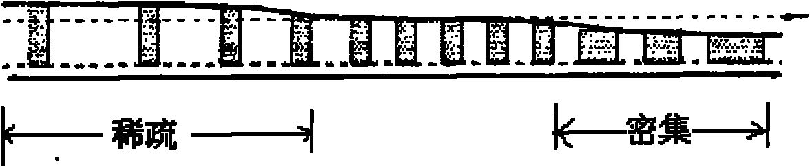
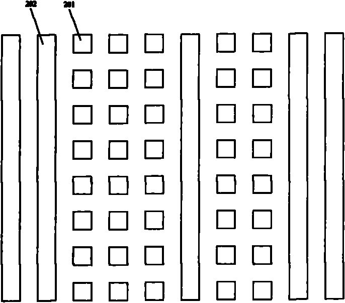
[0030] The core idea of ​​the present invention is to reduce the eddy current effect of the pattern filling structure and increase the quality factor of the inductor by optimizing the shape, size and interval of the pattern filling structure.

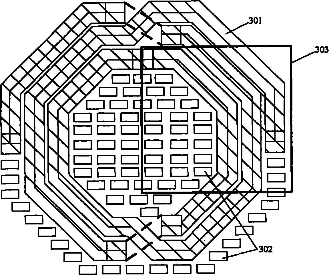
[0031] The main metal coil of the inductor is located on the top metal (Top Metal) layer to image 3 Taking a differential inductor with 3 terminals as an example, a pattern filler structure is inserted around the metal coil of the inductor, that is, the inner area and the outer area. The pattern filling structure is a square metal block, obviously the height of the metal block is equal to the height of the metal coil of the inductor. After research, it is found that when the side length of the square metal blo...


PUM


Abstract

The invention discloses a figure filler structure inserted about an inductor. The figure filler structure are characterized by a plurality of square metal blocks with the same height as an inductor metal coil, the square metal blocks are inserted in an inside area and an outside area of the inductor metal coil which is positioned on a top metal layer; the side length of the square metal block is equal to a first minimum design rule which is the minimum measurement allowed by the technology; the density of the figure filler structure is not less than a second minimum design rule which is the minimum value for the density of the figure filler structure; the distance between the square metal blocks can be any measurement value in the scope from a third minimum design rule to the maximum distance value which is the distance between the square metal blocks when the density of the figure filler structure is equal to the second minimum design rule; and the third minimum design rule is the minimum distance between metals allowed by the technology. The invented structure effectively enhances the quality factor of inductor.

Description

technical field [0001] The invention relates to the technical field of semiconductor manufacturing, in particular to a pattern filling structure inserted around an inductor. Background technique [0002] At present, integrated circuit devices include multiple metal layers, and the metal in each metal layer is distributed in the insulating material silicon dioxide layer according to different densities according to different applications of the device, and the metal material is generally copper. Since silicon dioxide is harder than metal copper, and when the metal copper filled in the silicon dioxide layer is chemically mechanically polished (CMP), a certain pressure needs to be applied. Under the action of pressure, the distribution of the metal copper layer is comparatively Sparse areas have a thinner thickness than areas where the metal copper layer is more densely distributed. There are metal copper with different density distribution in the silicon dioxide material laye...

Claims


Application Information

Patent Timeline
Patent Type & Authority Applications(China)
IPC IPC(8): H01L27/00H01L23/528
Inventor 何丹
Owner SEMICON MFG INT (SHANGHAI) CORP
Why Eureka
Try Eureka