Motor magnet ring and magnet for reducing eddy-current effect

A technology of eddy current effect and magnet ring, applied in the direction of magnetic circuit shape/style/structure, can solve the problems of reduced efficiency, increased motor energy consumption, difficult and time-consuming processing, etc., to improve performance and life, reduce stress concentration, and reduce eddy current effect of effect

Inactive Publication Date: 2019-06-21
甘长泉
View PDF8 Cites 4 Cited by
  • Summary
  • Abstract
  • Description
  • Claims
  • Application Information

AI Technical Summary

Problems solved by technology

[0004] Rare earth permanent magnets (SmCo and NdFeB) have been widely used in various types of high-efficiency and energy-saving motors due to their high magnetic energy product and high coercive force. body, and when used in motors, the magnets are usually large in size. In the high-frequency alternating magnetic field, strong eddy currents are likely to be generated, resulting in an increase in the heating temperature of the magnets, especially the NdFeB magnets whose magnetic properties are sensitive to temperature, are more likely to cause Reversible and irreversible magnetic losses increase the energy consumption of the motor and reduce the efficiency. In order to solve this problem, at present, in order to reduce the eddy current loss of the large magnet, the glue with insulating properties is used after cutting the large magnet into small pieces. Combined into a whole after bonding, the existing technology needs to glue and assemble small pieces of magnets, which is time-consuming and costly to process, and it is difficult to ensure good insulation after bonding; after bonding and assembling, it is difficult to ensure shape tolerance and dimensional accuracy of the magnets Poor; after magnetization, each small magnet is adjacently arranged with the same sex, there is a strong repulsive force, and there is also a large stress during use, and it is easy to fail when the bonding force is not strong

Method used


Image

  • Motor magnet ring and magnet for reducing eddy-current effect
  • Motor magnet ring and magnet for reducing eddy-current effect
  • Motor magnet ring and magnet for reducing eddy-current effect

Examples


Embodiment Construction

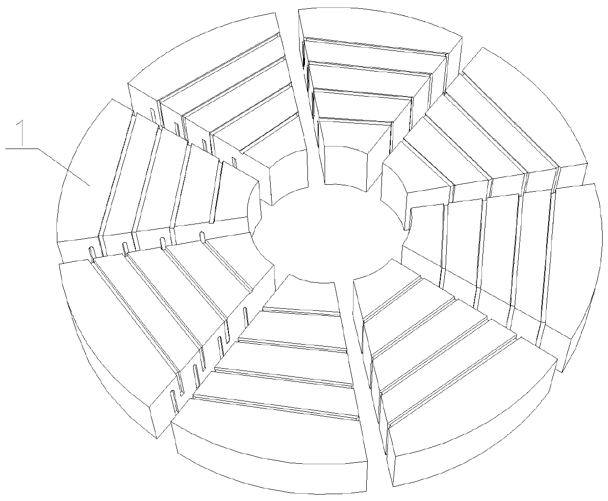
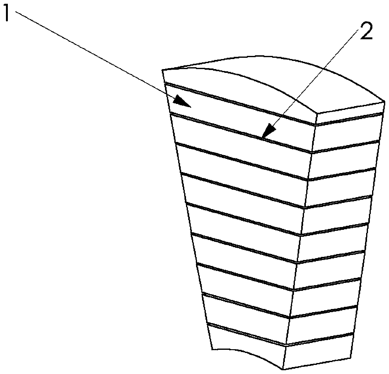
[0027] refer to figure 1 with figure 2 , a motor magnet ring that reduces eddy current effects according to the present invention, which includes magnets 1 arranged in a ring shape. Cutting grooves 2 are arranged on the magnets 1. The ends of the cutting grooves 2 do not intersect and overlap up and down. The end of the groove 2 is arc-shaped, and the magnet 1 is fan-shaped, and the end is arc-shaped. The cutting groove 2 is filled with epoxy glue, and it is characterized in that: the depth of the cutting groove 2 is 20% of the magnet 1 thickness.

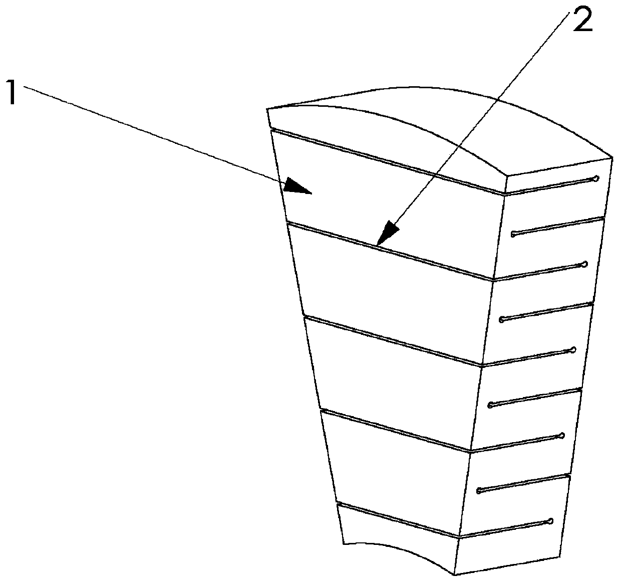
[0028] refer to image 3 , the present invention is a motor magnet for reducing eddy current effect. The magnet 1 is provided with at least one cutting groove 2 whose two ends do not intersect, the number of the cutting grooves 2 is four, and the ends of the cutting grooves 2 are Arc shape, the depth of the cutting groove 2 is 20% of the thickness of the magnet 1, the cutting groove 2 is filled with colloid, and the type of col...


PUM


Abstract

The present invention discloses a motor magnet ring and a magnet for reducing an eddy-current effect. The motor magnet ring comprises a magnet arranged in an annular shape. The magnet is provided witha cutting groove, and at least one cutting groove with two disjoint ends is arranged on the motor magnet. The invention can effectively increase the resistance of the magnet, effectively reduces theeddy-current effect in the magnet during the operation of the motor, reduces the heat generation and the thermal damage of the magnet and improves the efficiency of the motor. The invention can be widely applied to various permanent magnet motors.

Description

[0001] 【Technical field】 [0002] The invention relates to the technical field of motors, in particular to the technical field of a motor magnet ring and magnets for reducing eddy current effects. [0003] 【Background technique】 [0004] Rare earth permanent magnets (SmCo and NdFeB) have been widely used in various types of high-efficiency and energy-saving motors due to their high magnetic energy product and high coercive force. body, and when used in motors, the magnets are usually large in size. In the high-frequency alternating magnetic field, strong eddy currents are likely to be generated, resulting in an increase in the heating temperature of the magnets, especially the NdFeB magnets whose magnetic properties are sensitive to temperature, are more likely to cause Reversible and irreversible magnetic losses increase the energy consumption of the motor and reduce the efficiency. In order to solve this problem, at present, in order to reduce the eddy current loss of the lar...

Claims


Application Information

Patent Timeline
Patent Type & Authority Applications(China)
IPC IPC(8): H02K1/06
Inventor 甘长泉
Owner 甘长泉
Why Eureka
Try Eureka