Hairpin flat wire motor stator and hairpin flat wire motor

A technology for motor stators and hairpins, applied in electrical components, electromechanical devices, magnetic circuit shape/style/structure, etc., can solve the problem of difficulty in meeting motor performance design requirements, reducing the height and size of the outlet end, and complicated wiring of transition connecting lines. It can meet the requirements of motor performance design and manufacturing process design, the winding structure is simple and compact, and the effect of reducing high-speed skin effect

Active Publication Date: 2020-02-21
HEFEI JUYI POWER SYST CO LTD
View PDF7 Cites 12 Cited by
  • Summary
  • Abstract
  • Description
  • Claims
  • Application Information

AI Technical Summary

Problems solved by technology

However, domestic new energy vehicle drive motors are not only in the low-voltage platform development stage, but also continue to increase in speed, which makes it difficult for the flat wire winding scheme with a small number of parallel branches to meet the motor performance design requirements
Patent CN107408855 proposes a four-way parallel flat wire winding scheme, but the wiring of the transition connection line at the outlet end of this winding scheme is relatively complicated, and it is not conducive to reducing the height of the end of the outlet end, and there is no advantage of compact structure

Method used


Image

  • Hairpin flat wire motor stator and hairpin flat wire motor
  • Hairpin flat wire motor stator and hairpin flat wire motor
  • Hairpin flat wire motor stator and hairpin flat wire motor

Examples


Embodiment Construction

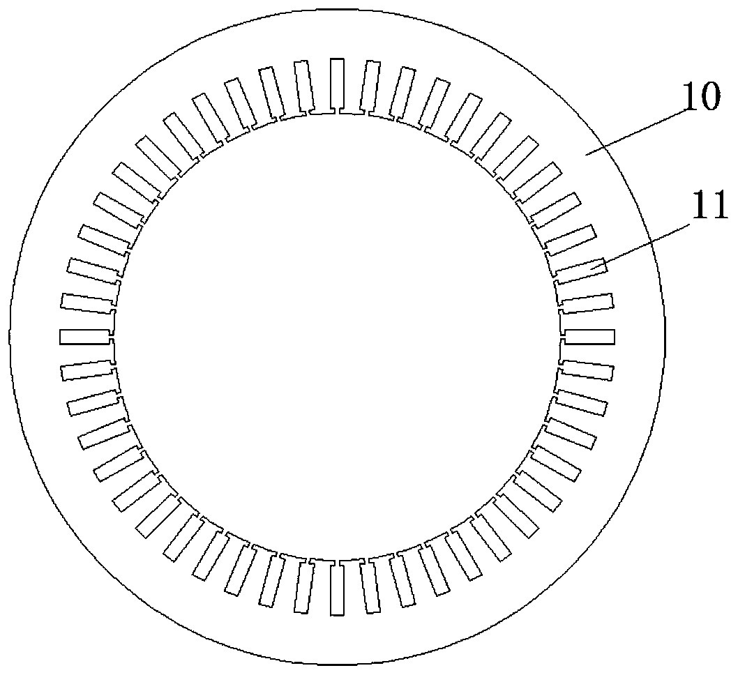
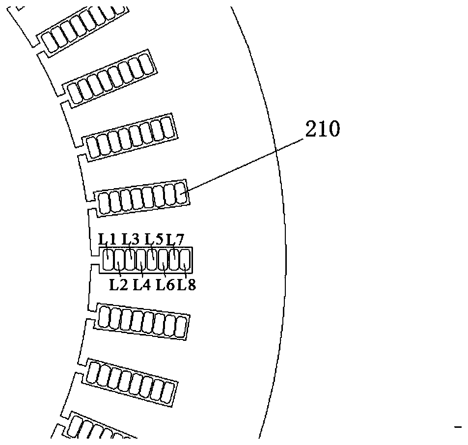
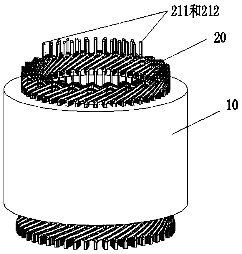
[0030] Also refer to Figure 1-Figure 3 , figure 1 It is a top structural schematic diagram of a stator core of a hairpin flat wire motor in some embodiments of the present invention. figure 2 It is a schematic diagram of the distribution of conductors in the slots of the stator core of the hairpin flat wire motor in some embodiments of the present invention. image 3 It is a three-dimensional structural view of the stator of the hairpin flat wire motor in some embodiments of the present invention. The stator of the hairpin flat wire motor includes: a stator core structure 10 and a stator winding 20 . Wherein, the inside of the stator core structure 10 is evenly spaced with a plurality of winding slots 11 extending along its axial direction, and the winding slots 11 are distributed with conductors 210 . One side of the two ends of the stator core 10 is the hairpin end of the winding, and the other side is the welding end of the winding. The stator winding 20 is composed ...


PUM


Abstract

The invention provides a hairpin flat wire motor stator and a hairpin flat wire motor; the hairpin flat wire motor stator comprises: a stator core structure, wherein the inner side of the stator corestructure is uniformly provided with a plurality of winding grooves extending along the axial direction of the stator core structure at intervals, one end face side of the stator core is a winding hairpin end, and the other end face side of the stator core is a winding welding end; stator windings that are arranged in the winding grooves, the stator windings comprise a first phase winding, a second phase winding and a third phase winding, and each of the first phase winding, the second phase winding and the third phase winding comprises four branches connected in parallel; input terminals andoutput terminals of the first phase winding, the second phase winding and the third phase winding are all distributed at the winding hairpin end. According to the invention, under the conditions of alow-voltage platform and high speed of an new energy automobile driving motor, the requirements of motor performance design and manufacturing manufacturability design can be better met.

Description

technical field [0001] The invention relates to the technical field of electric motors, in particular to a stator of a card-issuing flat-wire motor and a card-issuing flat-wire motor. Background technique [0002] The design of the flat wire motor winding scheme not only needs to meet the performance requirements of the motor, but also needs to consider the manufacturability of mass production. At present, the number of parallel branches in the design of the common flat wire motor winding scheme is small, so as to meet the requirements of motor performance design and manufacturing process design. However, domestic new energy vehicle drive motors are not only in the low-voltage platform development stage, but also continue to increase in speed, which makes it difficult for the flat wire winding scheme with a small number of parallel branches to meet the motor performance design requirements. Patent CN107408855 proposes a four-way parallel flat wire winding scheme, but the wi...

Claims


Application Information

Patent Timeline
Patent Type & Authority Applications(China)
IPC IPC(8): H02K1/16H02K3/12H02K3/28
CPCH02K1/16H02K3/12H02K3/28H02K2213/03
Inventor 刘蕾朱标龙田旭孙纯哲
Owner HEFEI JUYI POWER SYST CO LTD
Why Eureka
Try Eureka