Intelligent head-mounted device

A head-mounted device and smart technology, applied in the field of smart wear, can solve problems such as sound reduction, and achieve the effect of improving leakage reduction and low-frequency sensitivity.

Active Publication Date: 2020-02-21
GOERTEK INC
View PDF4 Cites 13 Cited by
  • Summary
  • Abstract
  • Description
  • Claims
  • Application Information

AI Technical Summary

Problems solved by technology

While reducing sound leakage, this solution has a certain acoustic short circuit in the sound of the front and rear sound chambers, mainly because the low frequency band is relatively serious, resulting in a relatively reduced sound received by the wearer.

Method used


Image

  • Intelligent head-mounted device
  • Intelligent head-mounted device
  • Intelligent head-mounted device

Examples


Embodiment 1

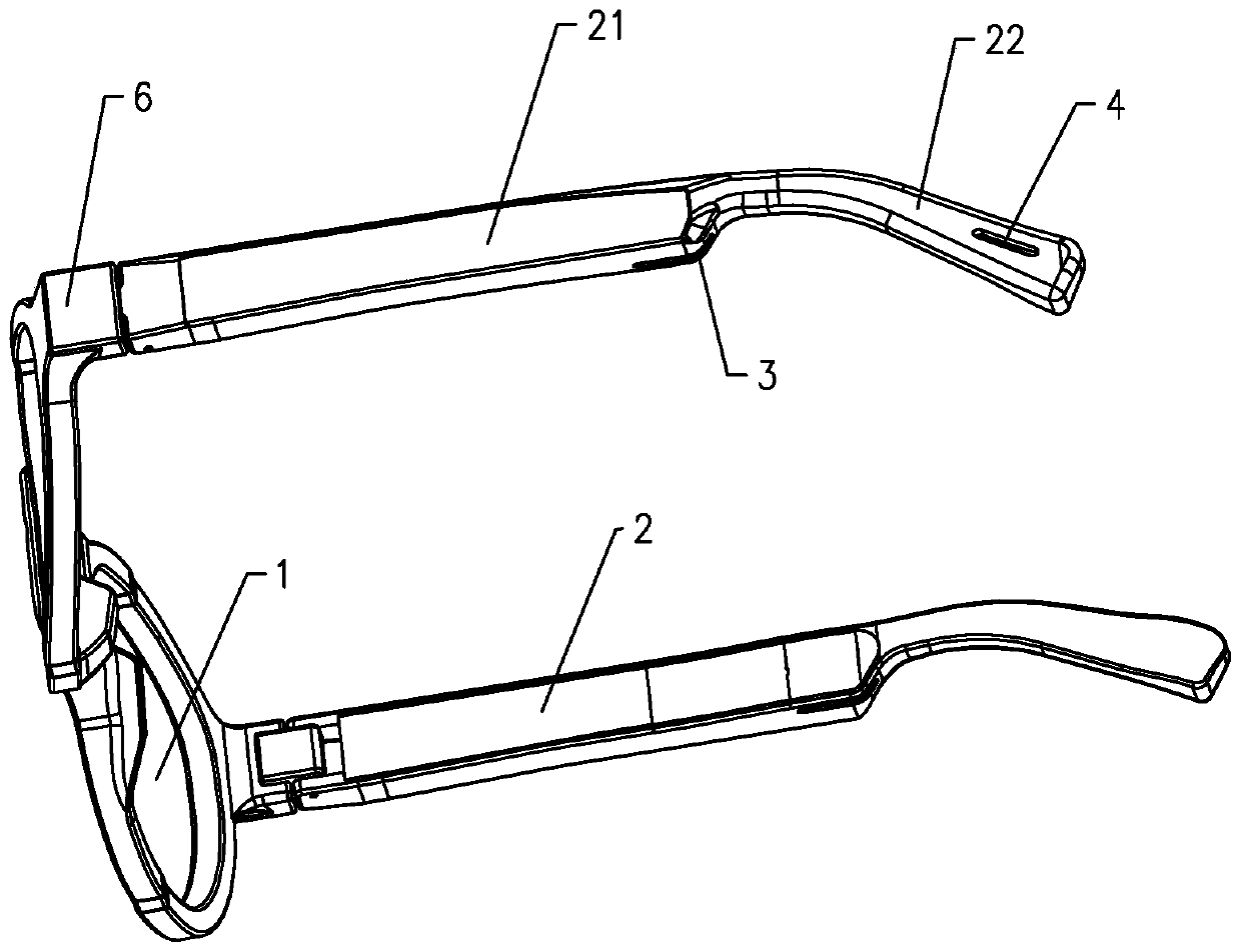
[0041] According to an embodiment of the present invention, a smart head-mounted device is provided. refer to figure 1 As shown, the smart head-mounted device includes at least one lens 1 and at least one leg 2, the lens 1 is connected to the leg 2; the leg 2 has a cavity; the smart head-mounted device also includes a sounding device , the sounding device is arranged in the cavity, and the sounding device divides the cavity into a front acoustic cavity and a rear acoustic cavity; a sound outlet 3 and a main sound leakage hole 4 are provided on the legs 2, Wherein, the sound outlet hole 3 communicates with the front acoustic cavity, and the main sound leakage hole 4 communicates with the rear acoustic cavity.

[0042] The intelligent head-mounted device of the present invention realizes the open coupling between the sound emitting device and the wearer's ear hole by setting the sound emitting device in the cavity of the leg 2. Compared with the in-ear closed coupling form, th...

Embodiment 2

[0057] This embodiment is a further improvement made on the basis of Embodiment 1, and is different from Embodiment 1 in that:

[0058] Such as Figure 4 As shown, in this embodiment, the leg 2 is also provided with a secondary sound leakage hole 5 connected to the rear acoustic cavity, and the position of the secondary sound leakage hole 5 on the leg 2 is configured so that when When the wearer wears the smart head-mounted device, the secondary sound leakage hole 5 is located on the front side of the wearer's auricle; and the distance between the secondary sound leakage hole 5 and the wearer's ear hole is greater than the outlet. The distance between the sound hole 3 and the wearer's ear hole.

[0059] In Embodiment 1, when only the main sound leakage hole 4 is provided, since the main sound leakage hole 4 is located on the rear side of the wearer's auricle, the distance between the main sound leakage hole 4 and the sound outlet 3 is limited by the overall structure. Relati...


PUM


Abstract

The invention discloses an intelligent head-mounted device, and the device comprises a lens and a leg part, the lens is connected with the leg part, and the leg part is internally provided with a cavity; the sound production device is arranged in the cavity, and the cavity is divided into a front sound cavity and a rear sound cavity by the sound production device; the sound outlet hole is formed in the leg part and is communicated with the front sound cavity; the main sound leakage hole and the auxiliary sound leakage hole are formed in the leg part, and the main sound leakage hole and the auxiliary sound leakage hole are communicated with the rear sound cavity; the positions of the sound outlet hole, the main sound leakage hole and the auxiliary sound leakage hole are configured as follows: when a wearer wears the intelligent head-mounted device, the sound outlet hole and the auxiliary sound leakage hole are located at the front side of the auricle of the wearer, and the main sound leakage hole is located at the rear side of the auricle of the wearer.

Description

technical field [0001] The present invention relates to the technical field of smart wearables, and more specifically, to a smart head-mounted device. Background technique [0002] With the development of science and technology, smart wearable devices have brought great convenience to people's lives, and as smart wearable devices, smart head-mounted devices are becoming more and more popular. Smart wearable devices can be regarded as a miniature smart A device that has corresponding functions for collecting, processing or displaying data. Users can install programs provided by software service providers such as software and games in smart headsets, and can also complete functions such as adding schedules, map navigation, interacting with friends, taking photos and videos, and making video calls with friends through voice or motion control , and wireless network access can also be realized through the mobile communication network. [0003] The sound-generating device on the...

Claims


Application Information

Patent Timeline
Patent Type & Authority Applications(China)
IPC IPC(8): H04R1/10H04R1/28G02C11/00
CPCH04R1/10H04R1/105H04R1/1058H04R1/28G02C11/10H04R1/2846H04R5/0335G02C11/06
Inventor 杨鑫峰翟成祥王苗苗
Owner GOERTEK INC
Why Eureka
Try Eureka