LED matrix dimming circuit and method and electronic equipment

A dimming circuit, matrix circuit technology, applied in the direction of electrical components, etc., can solve problems such as LED display light smear

Inactive Publication Date: 2020-02-21
SHENZHEN SKYWORTH RGB ELECTRONICS CO LTD
View PDF6 Cites 3 Cited by
  • Summary
  • Abstract
  • Description
  • Claims
  • Application Information

AI Technical Summary

Problems solved by technology

[0003] The main purpose of the present invention is to propose a LED matrix dimming circuit, LED matrix dimming method and electronic equipment, aiming to solve the problem of light smear in LED displays in the prior art

Method used


Image

  • LED matrix dimming circuit and method and electronic equipment
  • LED matrix dimming circuit and method and electronic equipment
  • LED matrix dimming circuit and method and electronic equipment

Examples


Embodiment Construction

[0034] It should be understood that the specific embodiments described here are only used to explain the present invention, not to limit the present invention.

[0035] The following will clearly and completely describe the technical solutions in the embodiments of the present invention with reference to the accompanying drawings in the embodiments of the present invention. Obviously, the described embodiments are only part of the embodiments of the present invention, not all of them. Based on the embodiments of the present invention, all other embodiments obtained by persons of ordinary skill in the art without creative efforts fall within the protection scope of the present invention.

[0036] It should be noted that all directional indications (such as up, down, left, right, front, back, etc.) in the embodiments of the present invention are only used to explain each If the relative positional relationship, movement conditions, etc. between the components change, the directi...


PUM


Abstract

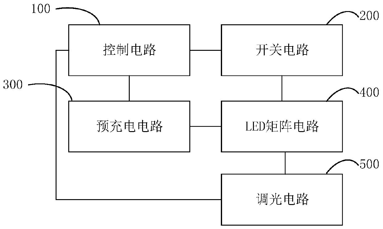
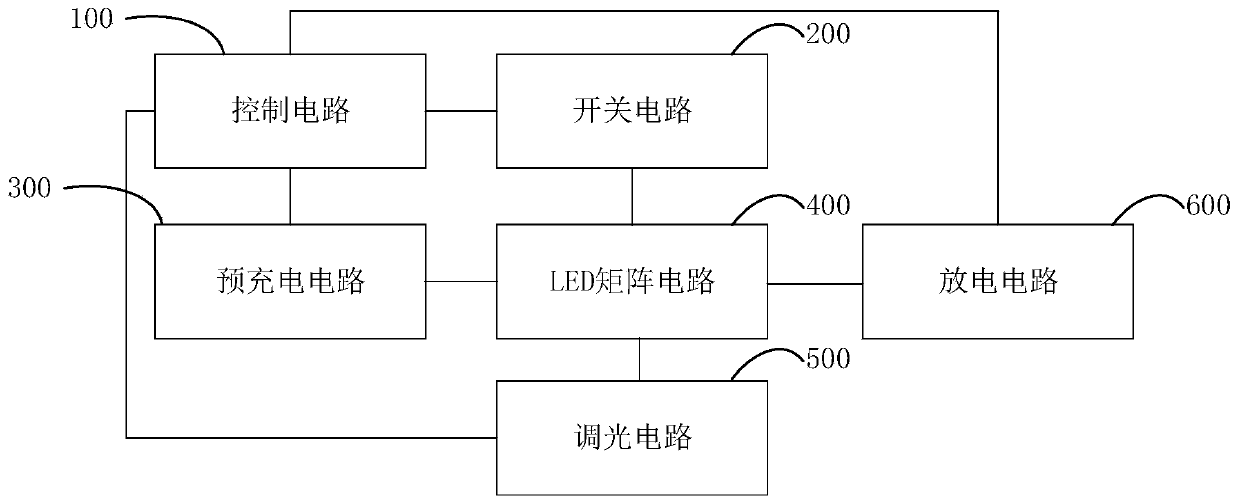
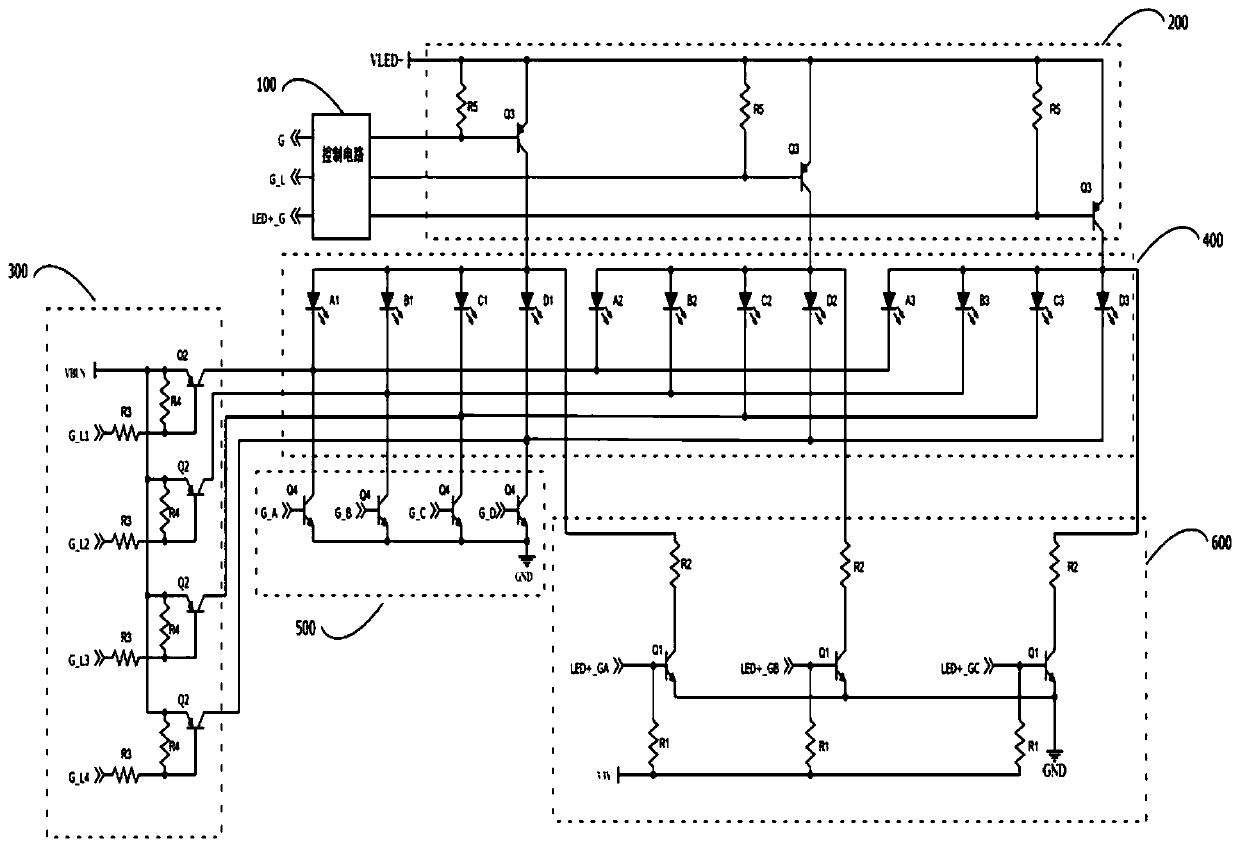
The invention provides an LED matrix dimming circuit, an LED matrix dimming method and electronic equipment. The LED matrix dimming circuit comprises a control circuit, a switching circuit, an LED matrix circuit, a dimming circuit and a pre-charging circuit. The control circuit is used for correspondingly outputting a first level signal and a second level signal to the switching circuit and the pre-charging circuit so as to control the pre-charging circuit to be switched on when the switching circuit is switched off. The pre-charging circuit is connected with the output end of the LED matrix circuit and is used for outputting charging voltage when the switching circuit is switched off. The dimming circuit is connected with the output end of the LED matrix circuit and used for receiving thedriving signal of the control circuit to adjust backlight current. By arranging the pre-charging circuit, when the switching circuit is switched off, the voltage of the negative end of the LED matrixcircuit is rapidly increased. The voltage difference of a corresponding LED is lower than the starting voltage, and the LED is rapidly switched off to avoid lamplight smear.

Description

technical field [0001] The invention relates to the technical field of LEDs, in particular to an LED matrix dimming circuit, an LED matrix dimming method and electronic equipment. Background technique [0002] In order to cope with the high cost and complex drive system of MINI LED and Micro LED in the display field, matrix dimming is increasingly used. However, due to the parasitic capacitance in the backlight LED system, when the backlight system is turned on or off In an instant, due to the discharge of the charge stored in the parasitic capacitor, the phenomenon of light smear (commonly known as ghosting) will appear in the backlight. This phenomenon has brought great trouble to our viewing experience and the improvement of image quality. Contents of the invention [0003] The main purpose of the present invention is to provide an LED matrix dimming circuit, LED matrix dimming method and electronic equipment, aiming to solve the problem of light smear in LED displays i...

Claims


Application Information

Patent Timeline
Patent Type & Authority Applications(China)
IPC IPC(8): H05B47/10
Inventor 姚志忠
Owner SHENZHEN SKYWORTH RGB ELECTRONICS CO LTD
Why Eureka
Try Eureka