


Quick Research
Generate reliable direction feasibility study reports for your R&D in just a few steps.

Technical Q&A
Discover and master advanced knowledge NOW. Basics, ideas, possibilities, all at once.

Find Solutions
As an expert in R&D theories, this can generate solutions to your technical problems instantly.

Evaluate Feasibility
Analyze your overall solution with one click, know your potential R&D risks in advance.

Monitor Landscape
Get weekly tech updates, stay abreast of the latest tech innovations and key insights.
Lock pin assembly, telescopic mechanism, protective fence and tool ladder
A technology of telescopic mechanism and guardrail, applied in the direction of ladders, building structures, buildings, etc., can solve the problem of difficult replacement, and achieve the effect of easy replacement
- Summary
- Abstract
- Description
- Claims
- Application Information
AI Technical Summary
Problems solved by technology
Method used
Image

Examples
Embodiment 1
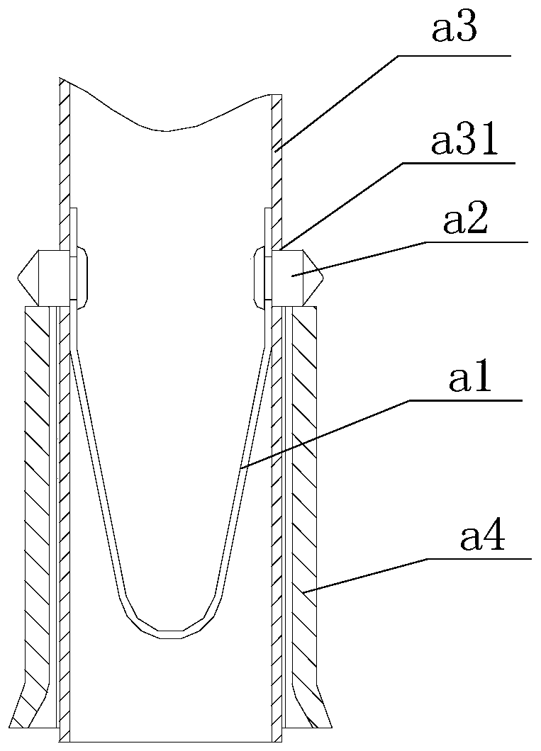
[0064] refer to figure 1 , in the prior art, the lock pin assembly usually includes a metal elastic piece a1 and a movable pin a2, which is shown as a telescoping mechanism installed with the lock pin assembly, including the lock pin assembly, the inner tube a3 and the sliding sleeve a4; the inner tube a3 passes through The sliding sleeve a4, and the inner pipe member a3 can slide relative to the sliding sleeve a4; a cavity is provided inside the inner pipe member a3, and an inner pipe member perforation a31 is opened on the pipe rod wall corresponding to the inner pipe member a3; the metal elastic sheet a1 is installed inside the cavity, and the movable pin a2 is installed inside the inner tube hole a31, and one end of the movable pin a2 is fixed to the metal elastic sheet a1. Under normal conditions, under the action of the metal elastic sheet a1, the other end of the movable pin a2 passes through the inner tube through the inner tube a31 to limit the position of the sliding...
Embodiment 2
[0078] This embodiment provides a telescopic mechanism, refer to Figure 5 , the telescoping mechanism includes an inner rod 5, a sleeve 6 and the locking pin assembly provided in any one of the first embodiment.
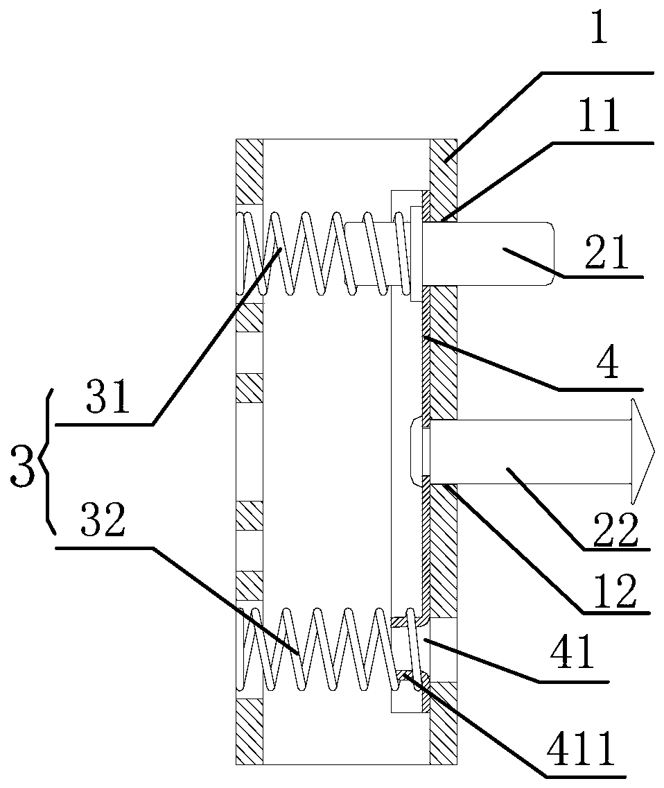
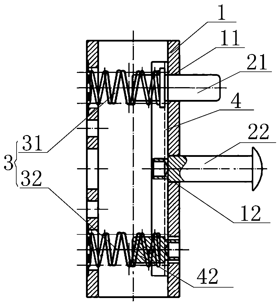
[0079] Wherein, the inner rod 5 passes through the sleeve 6, and the inner rod 5 can slide relative to the sleeve 6; the inside of the inner rod 5 is provided with a cavity, and the inner rod 5 is provided with an inner rod on the rod wall corresponding to the cavity. Limit hole 51, the inner rod limit hole 51 runs through the rod wall of the inner rod 5; the sleeve 1 is installed in the cavity, and the lock pin 21 is configured such that in the initial state, the lock pin 21 penetrates the lock pin hole 11 and the inner rod limit The position hole 51 , the second end of the lock pin 21 is located outside the inner rod limit hole 51 to limit the position of the inner rod 5 relative to the sleeve 6 .
[0080] There are many ways to limit the position of the inner ro...
Embodiment 3
[0084] This embodiment provides a kind of guardrail, refer to Image 6 and Figure 7 , the guardrail includes a first support rod 71 , a second support rod 72 and a fence 73 , and the fence 73 is installed between the first support rod 71 and the second support rod 72 . The guardrail also includes two telescopic mechanisms provided in the second embodiment; wherein, the inner rod 5 of one telescopic mechanism forms the first support rod 71, and the inner rod 5 of the other telescopic mechanism forms the second support rod 72. Each sleeve 6 of the mechanism is provided with an installation structure, and the installation structure is configured to be able to install the sleeve 6 on the tool ladder.
[0085] When installing, the two sleeves 6 can be installed on both sides of the tool ladder respectively, and then the two inner rods 5 can be respectively assembled inside the two sleeves 6 and positioned with the lock pin assembly to install the guardrail. For the tool ladder, ...
PUM
 Abstract
Description
Claims
Application Information
 - R&D Engineer
- R&D Manager
- IP Professional
- Industry Leading Data Capabilities
- Powerful AI technology
- Patent DNA Extraction
Browse by: Latest US Patents, China's latest patents, Technical Efficacy Thesaurus, Application Domain, Technology Topic, Popular Technical Reports.
© 2024 PatSnap. All rights reserved.Legal|Privacy policy|Modern Slavery Act Transparency Statement|Sitemap|About US| Contact US: help@patsnap.com