Inner cold and hot air circulation device of power distribution cabinet

A technology of air circulation and power distribution cabinets, which is applied in substation/power distribution device housing, substation/switchgear cooling/ventilation, substation/switch layout details, etc., which can solve the problems of low heat dissipation efficiency, poor heat dissipation of power distribution cabinets, Low performance and other problems, to achieve the effect of reasonable structure setting, not easy to safety accidents, high heat dissipation efficiency

Active Publication Date: 2020-02-25
浙江德塔森特数据技术有限公司
View PDF3 Cites 4 Cited by
  • Summary
  • Abstract
  • Description
  • Claims
  • Application Information

AI Technical Summary

Problems solved by technology

[0003] 1. In the prior art, the overall heat dissipation of the power distribution cabinet is poor, and it is often directly installed on one side of the power distribution cabinet to dissipate heat. Heat dissipation, the internal cold and hot air circulation of the power distribution cabinet cannot be carried out to dissipate heat, and the heat dissipation is low;
[0004] 2. In the existing technology, the power distribution cabinet often uses air cooling for direct heat dissipation, and the heat dissipation efficiency is low, and the wind that enters the power distribution cabinet from the outside for heat dissipation may have a high temperature itself and cannot achieve the cooling effect

Method used


Image

  • Inner cold and hot air circulation device of power distribution cabinet
  • Inner cold and hot air circulation device of power distribution cabinet
  • Inner cold and hot air circulation device of power distribution cabinet

Examples


Embodiment Construction

[0031] The following will clearly and completely describe the technical solutions in the embodiments of the present invention with reference to the accompanying drawings in the embodiments of the present invention. Obviously, the described embodiments are only some, not all, embodiments of the present invention. Based on the embodiments of the present invention, all other embodiments obtained by persons of ordinary skill in the art without making creative efforts belong to the protection scope of the present invention.

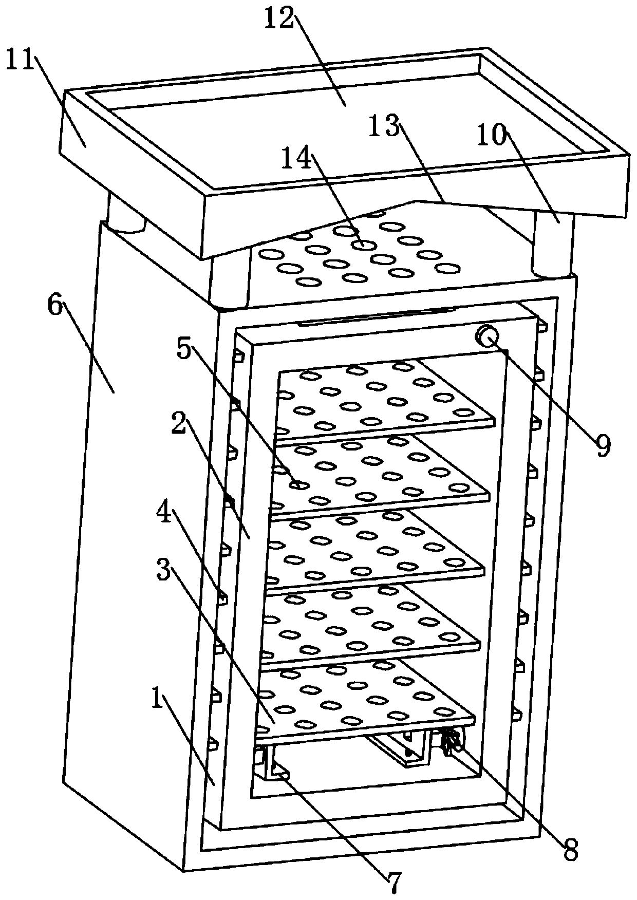
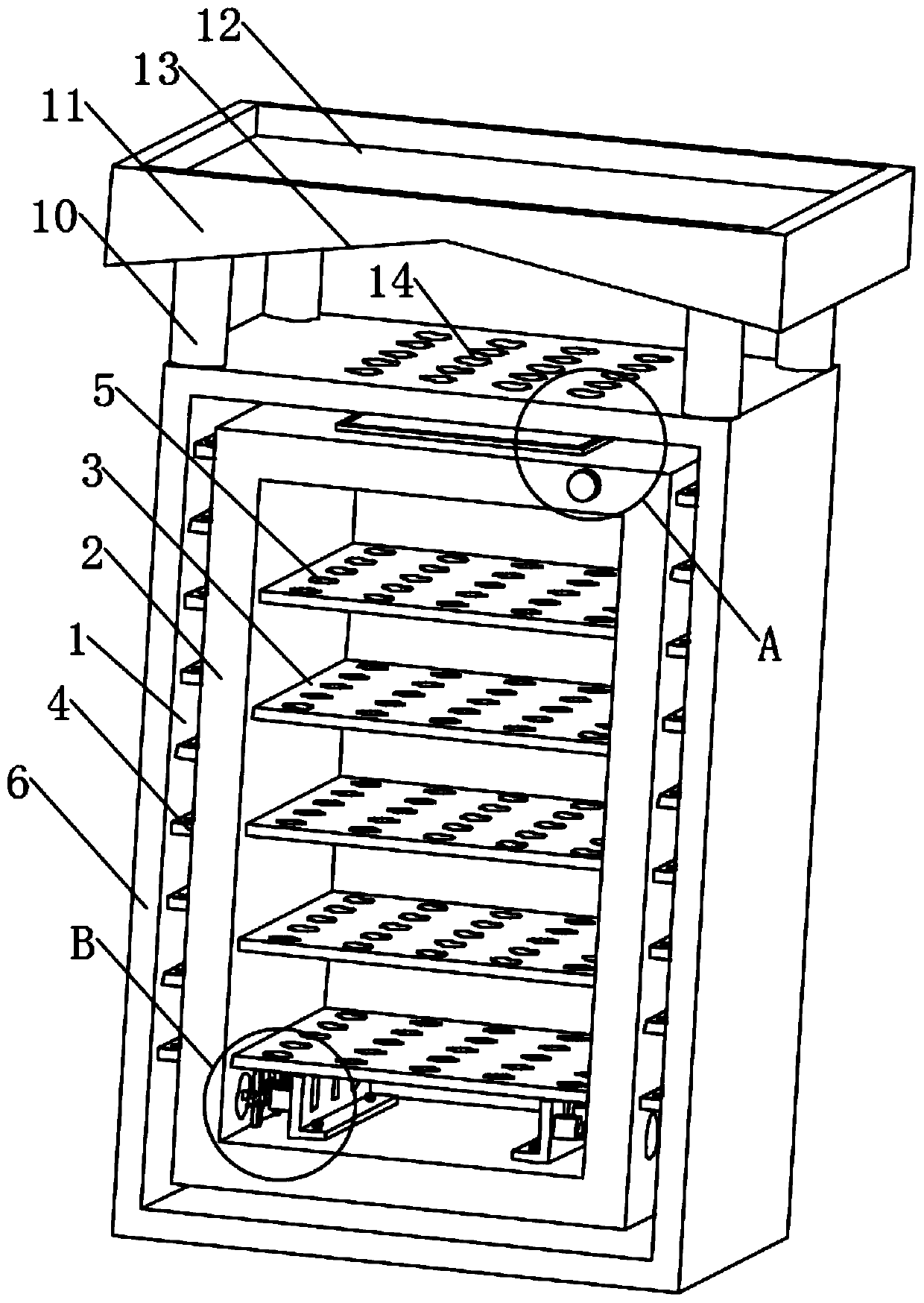
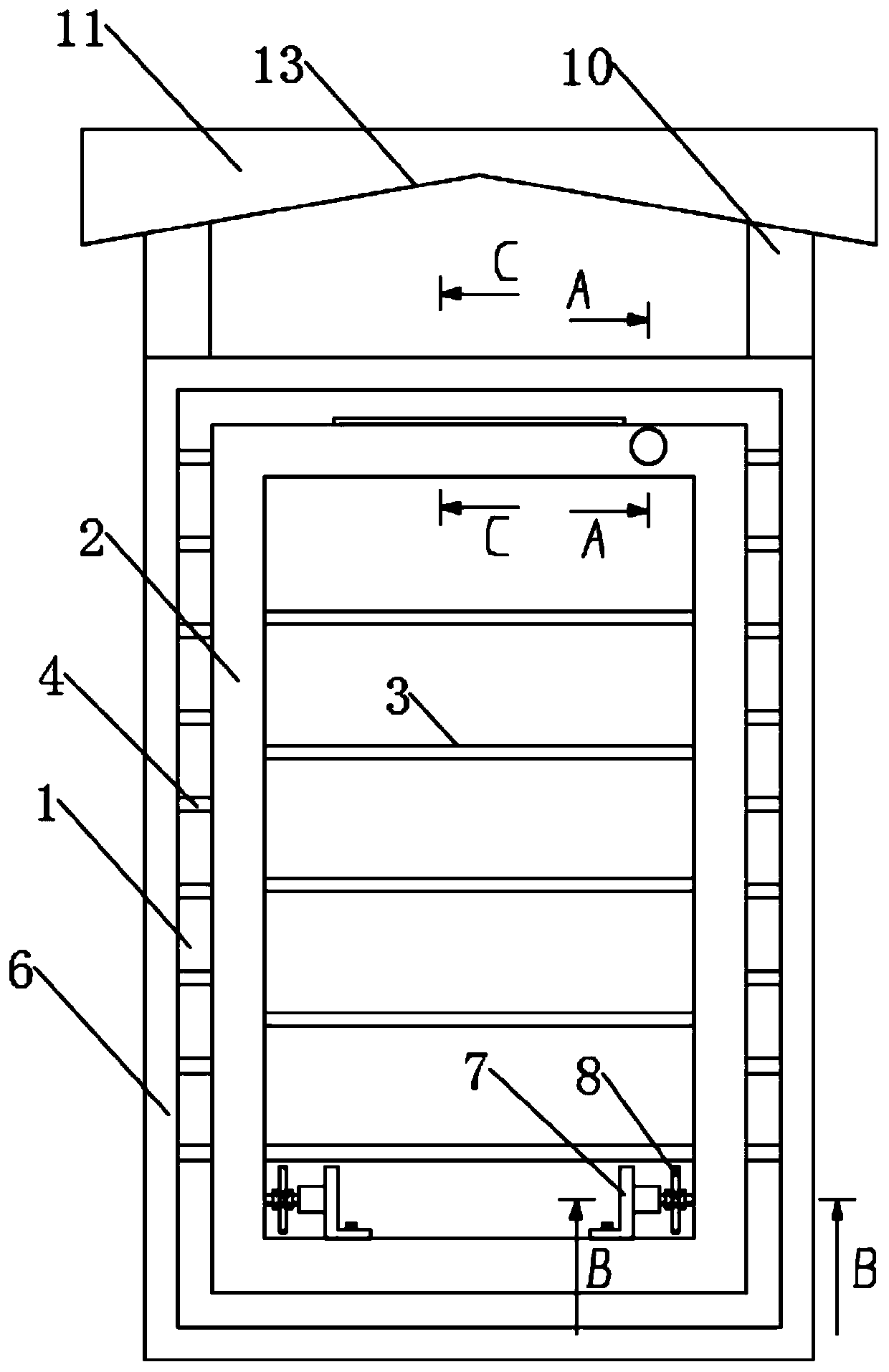
[0032] see Figure 1 to Figure 8 , the present invention provides a technical solution: an internal hot and cold air circulation device of a power distribution cabinet, including a hot and cold air circulation channel 1, and the hot and cold air circulation channel 1 is formed by the gap between the inner cabinet 2 and the outer cabinet 6 The upper end of the outer cabinet 6 is provided with a hot and cold air inlet and outlet 14 connected internally and exter...


PUM


Abstract

The invention relates to the technical field of power distribution cabinets and particularly relates to an inner cold and hot air circulation device of a power distribution cabinet, which comprises acold and hot air circulation channel. The cold and hot air circulation channel is composed of a gap between an inner cabinet body and an outer cabinet body; a plurality of sets of metal heat exchangeplates are arranged in the cold and hot air circulation channel; a plurality of sets of vertically-arranged containing plates are arranged in the inner cabinet body; and a plurality of sets of vertically-communicated heat dissipation holes are formed in the surfaces of the containing plates. The cold and hot air circulation channel is designed between the outer cabinet and the inner cabinet, and the cold and hot air circulation channel can achieve the purpose of good inner cold and hot air circulation heat dissipation among the inner cabinet, the outer cabinet and the inner cabinet; a coolingwater cavity is formed in the middle layer of the inner wall of the inner cabinet body, heat dissipation is achieved through combination of air cooling and water cooling, the overall heat dissipationefficiency is high, water and electricity of the cooling water cavity in the inner cabinet body are separated, safety accidents are not likely to happen, and cooling machine oil can be added into thecooling water cavity to be used for cooling.

Description

technical field [0001] The invention relates to the technical field of power distribution cabinets, in particular to an internal cold and hot air circulation device of a power distribution cabinet. Background technique [0002] The power distribution cabinet is the general name of the motor control center. The power distribution cabinet is used in the occasions where the load is relatively scattered and there are few circuits; the motor control center is used in the occasions where the load is concentrated and there are many circuits. There are still the following disadvantages: [0003] 1. In the prior art, the overall heat dissipation of the power distribution cabinet is poor, and it is often directly installed on one side of the power distribution cabinet to dissipate heat. Heat dissipation, the internal cold and hot air circulation of the power distribution cabinet cannot be carried out to dissipate heat, and the heat dissipation is low; [0004] 2. In the prior art, t...

Claims


Application Information

Patent Timeline
Patent Type & Authority Applications(China)
IPC IPC(8): H02B1/56H02B1/28
CPCH02B1/28H02B1/565
Inventor 张良
Owner 浙江德塔森特数据技术有限公司
Why Eureka
Try Eureka