Balloon catheter placement rack for department of cardiology
A balloon catheter and cardiology technology, applied in the field of medical devices, can solve problems such as affecting the normal operation of the operation, cross-contamination, and reducing the safety of the operation, and achieve the effects of reducing the risk of mutual cross-contamination, preventing mildew, and reducing humidity.
- Summary
- Abstract
- Description
- Claims
- Application Information
AI Technical Summary
Problems solved by technology
Method used
Image

Examples
Embodiment Construction
[0022] The following will clearly and completely describe the technical solutions in the embodiments of the present invention with reference to the accompanying drawings in the embodiments of the present invention. Obviously, the described embodiments are only some, not all, embodiments of the present invention.
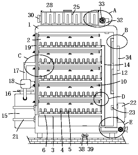
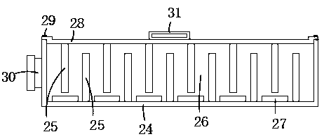
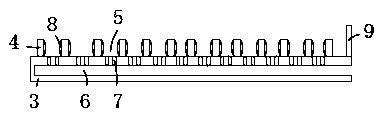
[0023] refer to Figure 1-8 , a placement rack for balloon catheters in the Department of Cardiology, including a box body 1, a box door is arranged in the opening on one side of the box body 1 by means of loose-leaf rotation, and a seal made of rubber material is fixed on the inside of the box door close to the box body 1 The door frame strip, the box door can be used to seal the interior of the placement rack after the cardiology balloon catheter is placed in the placement rack, so as to prevent external dust and other debris from entering the placement rack and pollute the cardiology balloon catheter. The inside of the body 1 is provided with a placement cavity 2,...
PUM
 Abstract
Description
Claims
Application Information
 - R&D
- Intellectual Property
- Life Sciences
- Materials
- Tech Scout
- Unparalleled Data Quality
- Higher Quality Content
- 60% Fewer Hallucinations
Browse by: Latest US Patents, China's latest patents, Technical Efficacy Thesaurus, Application Domain, Technology Topic, Popular Technical Reports.
© 2025 PatSnap. All rights reserved.Legal|Privacy policy|Modern Slavery Act Transparency Statement|Sitemap|About US| Contact US: help@patsnap.com