Filter element integration device

An integrated device and filter element technology, applied in ultrafiltration, semi-permeable membrane separation, chemical instruments and methods, etc., can solve problems affecting normal work, ultrafiltration membrane knotting, rod imbalance, etc. The effect of slipping and preventing slipping

Inactive Publication Date: 2020-02-28
湖南时远新材料科技有限公司
View PDF7 Cites 0 Cited by
  • Summary
  • Abstract
  • Description
  • Claims
  • Application Information

AI Technical Summary

Problems solved by technology

[0004] During the production process of the ultrafiltration membrane module, one end needs to be hung high and straightened, and then the storage part of the ultrafiltration membrane module is installed on the drooping free end. In the prior art, people often hang the hollow ultrafiltration membrane directly on the pole Then lift the pole to a high place. During this process, the ultrafiltration membrane may become knotted, affecting the normal work, and the pole may also be unbalanced, causing the ultrafiltration membrane to slip.

Method used


Image

  • Filter element integration device
  • Filter element integration device
  • Filter element integration device

Examples


Embodiment 1

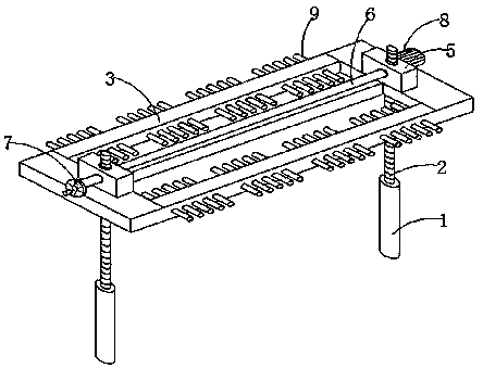
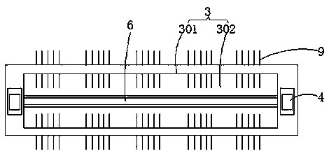
[0024] Such as Figure 1-4 As shown, a filter element integration device includes two support bottom rods 1 and a threaded rod 2 located at the upper end of the support bottom rod 1, the lower end of the support bottom rod 1 is fixedly installed on the ground, and the threaded rod 2 is vertically fixed and installed on the support bottom On the upper end of the rod 1, a bracket 3 is movable between the two threaded rods 2. The left and right ends of the bracket 3 are provided with sliding grooves 4 up and down. The threaded rod 2 and the sliding groove 4 are in clearance fit. The gear assembly 5, the steering gear assembly 5 includes a protective shell 501, the inner rotation of the protective shell 501 is equipped with a steering gear 502, the upper and lower ends of the protective shell 501 are provided with a first circular hole 503, and the left and right ends are provided with a second circular hole 504 , the threaded rod 2 passes through the two first round holes 503, an...

Embodiment 2

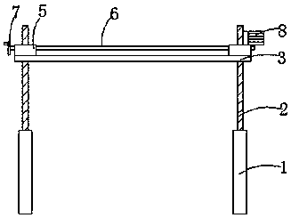
[0027] Such as Figure 1-5 As shown, a filter element integration device includes two support bottom rods 1 and a threaded rod 2 located at the upper end of the support bottom rod 1, the lower end of the support bottom rod 1 is fixedly installed on the ground, and the threaded rod 2 is vertically fixed and installed on the support bottom On the upper end of the rod 1, a bracket 3 is movable between the two threaded rods 2. The left and right ends of the bracket 3 are provided with sliding grooves 4 up and down. The threaded rod 2 and the sliding groove 4 are in clearance fit. The gear assembly 5, the steering gear assembly 5 includes a protective shell 501, the inner rotation of the protective shell 501 is equipped with a steering gear 502, the upper and lower ends of the protective shell 501 are provided with a first circular hole 503, and the left and right ends are provided with a second circular hole 504 , the threaded rod 2 passes through the two first round holes 503, an...


PUM


Abstract

The invention provides a filter element integration device, and belongs to the field of filter element integration devices. The filter element integration device comprises two supporting bottom rods and threaded rods located at the upper ends of the supporting bottom rods; a support is movably arranged between the two threaded rods; sliding grooves are vertically formed in the left end and the right end of the support in a penetrating mode, steering gear assemblies are arranged at the upper ends of the two ends of the support, a transmission shaft is movably arranged between the left steeringgear assembly and the right steering gear assembly, a hand-cranking wheel is arranged at one end of the transmission shaft, and a motor is fixedly installed at the other end of the transmission shaftand a protective shell; and hooks are arranged on the support. According to the filter element integration device, the threaded rods are adopted to match the upward steering gear assemblies and the transmission shaft, so that the support can move up and down on the threaded rods smoothly; the motor and the hand-cranking wheel are adopted, so that lifting of the support can be manually controlled,and lifting of the support can also be driven by the motor,; the whole device is simple in structure, a filter element can be hung high and straightened, the phenomena of shaking and knotting do not occur, and the filter element is not prone to sliding off in the hanging process; the filter element integration device is stable, efficient and high in practicability.

Description

technical field [0001] The invention relates to the field of filter element integration devices, in particular to a filter element integration device. Background technique [0002] The filter element separates solid particles in liquid or gas, or fully contacts different material components to speed up the reaction time, which can protect the normal operation of the equipment or the cleanliness of the air. When the fluid enters the filter element with a certain specification filter, its impurities are blocked. , while clean fluid exits through the filter element. The liquid filter element makes the liquid (including oil, water, etc.) clean the polluted liquid to the state required for production and life, that is, to make the liquid reach a certain degree of cleanliness. [0003] The air filter makes the polluted air clean to the state required for production and life, that is, to make the air reach a certain degree of cleanliness. [0004] During the production process ...

Claims


Application Information

Patent Timeline
Patent Type & Authority Applications(China)
IPC IPC(8): B01D63/02B01D61/14
CPCB01D61/145B01D63/021
Inventor 王红卫李涓胜
Owner 湖南时远新材料科技有限公司
Why Eureka
Try Eureka