Lifting spray head of automatic glue spraying machine

A technology of automatic glue spraying machine and spray head, which is applied in the field of glue spraying machine, can solve the problem that it is not suitable for gluing on non-planar parts, and achieve the effect of simple structure and high glue spraying quality

Active Publication Date: 2020-02-28
台州金荣企业管理合伙企业(有限合伙)
View PDF5 Cites 0 Cited by
  • Summary
  • Abstract
  • Description
  • Claims
  • Application Information

AI Technical Summary

Problems solved by technology

[0003] The purpose of the present invention is to provide a lifting nozzle of an automatic glue spraying machine to solve the technical problem that the existing equipment is not suitable for gluing on non-planar parts

Method used


Image

  • Lifting spray head of automatic glue spraying machine

Examples


Embodiment Construction

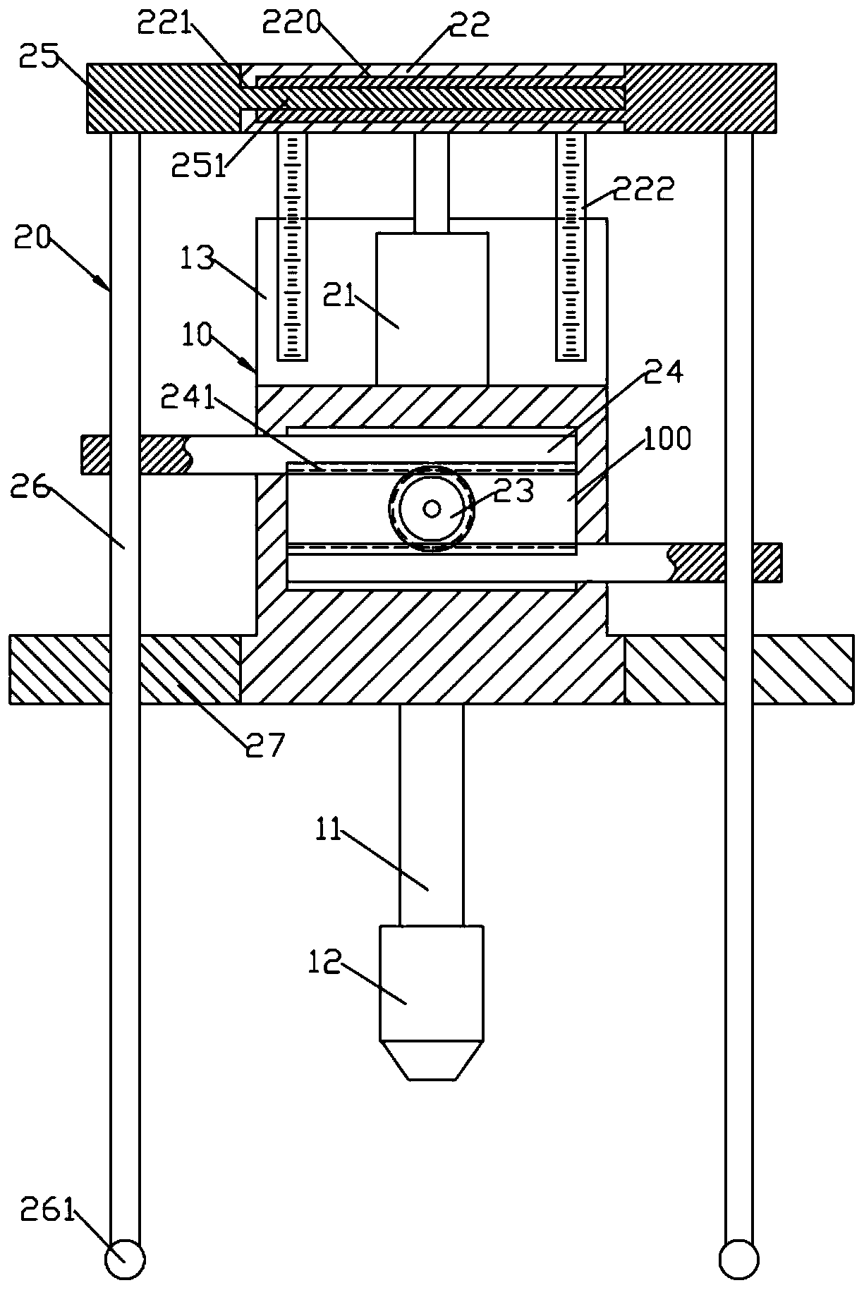
[0014] Such as figure 1 As shown, a lifting nozzle of an automatic glue spraying machine includes a nozzle support 10 and a nozzle limiter 20; the movable lift of the nozzle support 10 is set on the automatic glue sprayer and moves horizontally with the automatic glue sprayer; the nozzle limiter 20 includes a lifting support plate 22 arranged on the nozzle support 10; the left and right ends of the lifting support plate 22 move horizontally respectively to set a limit upper support plate 25; a pair of limit upper support plates 25 are synchronously separated or approached; A cylindrical limit rod 26 is formed on the lower end surface of the upper support plate 25; a nozzle support rod 11 is installed on the lower end surface of the nozzle support 10; a nozzle 12 is detachably installed on the lower end of the nozzle support rod 11; the limit rod The lower end of 26 is positioned at the lower side of nozzle 12 and a pair of limit rods 26 and nozzle 12 are on the vertical plane ...


PUM


Abstract

The invention discloses a lifting spray head of an automatic glue spraying machine. The lifting spray head comprises a spray head support and a spray head limiting device; the spray head support is arranged on the automatic glue spraying machine in a movable lifting manner and horizontally moves along with the automatic glue spraying machine; the spray head limiting device comprises a lifting supporting plate which is arranged on the spray head support in a lifting manner; limiting upper supporting plates are horizontally and correspondingly arranged at the left end and the right end of the lifting supporting plate; the pair of limiting upper supporting plates synchronously gets far away from or close to each other; cylindrical limiting rods are formed on the lower end surface of the limiting upper supporting plates; a nozzle supporting rod is mounted on the lower end surface of the spray head support; a nozzle is detachably mounted at the lower end of the nozzle supporting rod; the lower ends of the limiting rods are positioned on the lower side of the nozzle; and the pair of limiting rods and the nozzle are positioned on the same vertical plane in the left-right direction.

Description

technical field [0001] The invention relates to the field of glue spraying machines, in particular to a lifting nozzle of an automatic glue spraying machine. Background technique [0002] According to the prior art, the nozzle of the glue spraying machine adopts the mode of moving horizontally to smear liquid glue on the product. When the nozzle is moving horizontally, if it encounters a non-planar shape, such as a concave-convex surface, the non-planar shape will block the stroke of the nozzle, resulting in that the non-planar shape of the product surface cannot be glued. Contents of the invention [0003] The purpose of the present invention is to provide a lifting nozzle of an automatic glue spraying machine to solve the technical problem that the existing equipment is not suitable for gluing on non-planar parts. [0004] The technical solution of the present invention to solve the above technical problems is as follows: a lifting nozzle of an automatic glue spraying m...

Claims


Application Information

Patent Timeline
Patent Type & Authority Applications(China)
IPC IPC(8): B05B13/04B05B15/62B05B15/68
CPCB05B13/041B05B15/62B05B15/68
Inventor 谢浔
Owner 台州金荣企业管理合伙企业(有限合伙)
Why Eureka
Try Eureka