
A clamping and turning mechanism and a manipulator

A flipping mechanism and material clamping technology, applied in the field of manipulators, can solve the problems of low work efficiency of construction workers, smashed construction workers, and weak fixation.

Active Publication Date: 2020-06-26
GUANGDONG POWER GRID CO LTD DONGGUAN POWER SUPPLY BUREAU +1
View PDF6 Cites 0 Cited by
  • Summary
  • Abstract
  • Description
  • Claims
  • Application Information

AI Technical Summary

Problems solved by technology

[0005] For this reason, the embodiment of the present invention provides a material clamping and turning mechanism and a manipulator to solve the problem that in the prior art, the outer wall of the object is smooth and there are parts (such as screws, etc.) that are not firmly fixed on the surface. The 180-degree flip of the flipping device can easily cause the material or small parts to be thrown out, resulting in the material being broken or the construction personnel being hit; and most flipping devices can only flip at a fixed angle during the flipping process. Once the manipulator When the angle of the clamped workpiece needs to be turned changes, the construction personnel need to adjust the turning mechanism on the entire manipulator, but this operation will make the work efficiency of the construction personnel low.

Method used


Image

  • A clamping and turning mechanism and a manipulator
  • A clamping and turning mechanism and a manipulator
  • A clamping and turning mechanism and a manipulator

Examples


Embodiment Construction

[0034] The implementation mode of the present invention is illustrated by specific specific examples below, and those who are familiar with this technology can easily understand other advantages and effects of the present invention from the contents disclosed in this description. Obviously, the described embodiments are a part of the present invention. , but not all examples. Based on the embodiments of the present invention, all other embodiments obtained by persons of ordinary skill in the art without making creative efforts belong to the protection scope of the present invention.

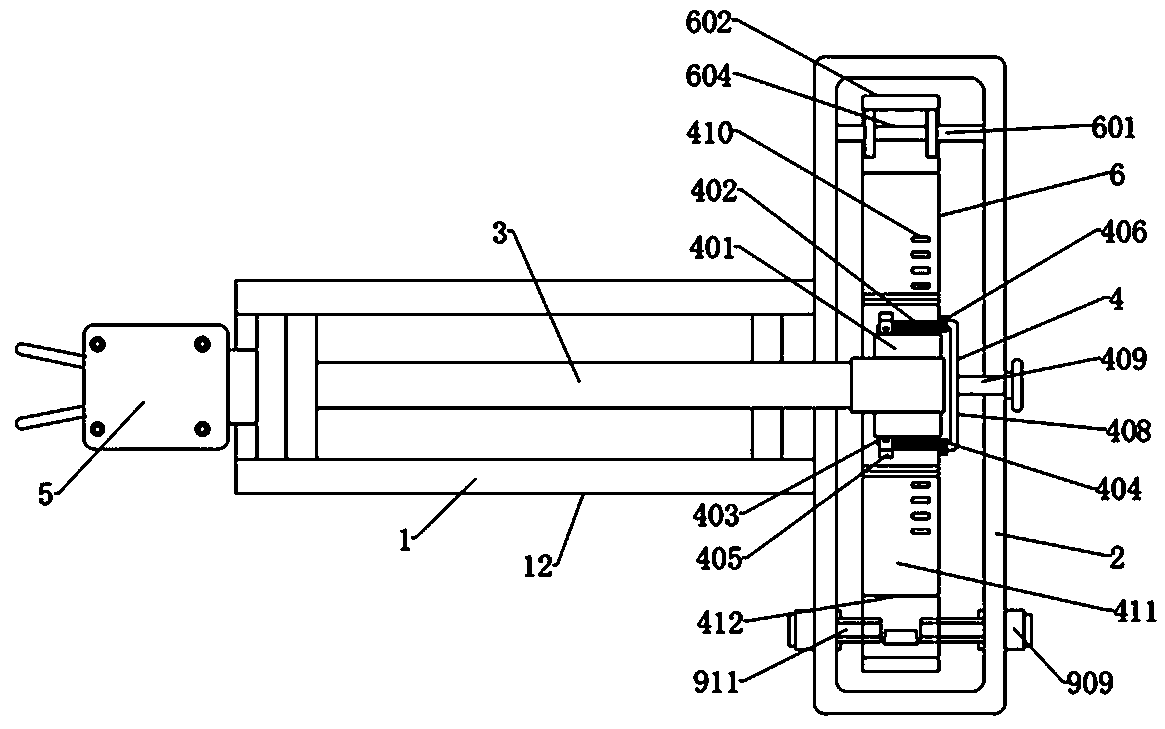
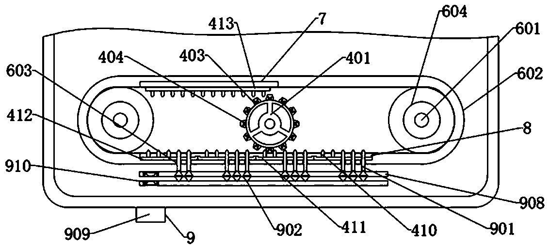
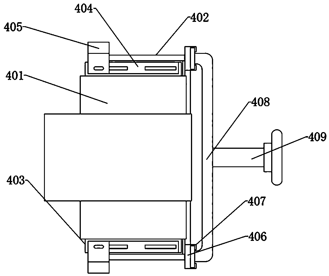
[0035] Such as figure 1 As shown, the present invention provides a material clamping and turning mechanism, which uses several partition blocks 411 and movable moving engagement blocks 405, so that the material can be turned over directly to the required angle at one time and turned over intermittently. Switch between the operations at the desired angle (that is, the amplitude and speed of the f...


PUM


Abstract

The embodiment of the invention discloses a material clamping turnover mechanism and a manipulator. The turnover mechanism comprises a mechanical arm barrel and a mounting cover arranged at the end portion of the mechanical arm barrel; a turnover rod is connected with the inner wall of the mechanical arm barrel in a sleeved mode, one end of the turnover rod penetrates into the mounting cover and aswitching mechanism is arranged on the side wall of the end portion of the turnover rod, and the other end of the turnover rod is connected with a material clamping clamp; and the inner wall of the mounting cover is provided with a driving belt driven by a driving device. According to the turnover mechanism and the manipulator, through partition blocks and moving meshing blocks, the operation ofturning over material to a required angle at a time and the operation of intermittently turning over the material to a required angle can be switched with each other, and even if an object with a smooth outer wall and with an unfixed part existing on the surface is encountered, the situation that the material or the part is thrown out can be avoided; and meanwhile, through the cooperation of a lifting tooth block and a pushing adjusting strip, the angle of the material in each intermittent turning over process can be freely changed, and the whole turnover mechanism does not need to be adjusted, so that the machining efficiency is improved.

Description

technical field [0001] Embodiments of the present invention relate to the field of manipulators, and in particular to a material-clamping and turning mechanism and a manipulator. Background technique [0002] A manipulator is an automatic operating device that can imitate certain movement functions of the human hand and arm to grab, carry objects or operate tools according to a fixed program. It has many structural components, such as mechanical seats, mechanical arms, and mechanical clamps. , but some manipulators need to turn over after clamping the material, so that the processing position of the material can be quickly adjusted. When the existing manipulators achieve the purpose of turning over, most of them drive gears through motors to make the manipulator rotate directly. 180 degree. [0003] But there are some problems with this operation: [0004] During the clamping process of some materials, if the outer wall of the large volume is smooth and there are parts (su...

Claims


Application Information

Patent Timeline
Patent Type & Authority Patents(China)
IPC IPC(8): B25J9/00B25J9/10
CPCB25J9/00B25J9/10B25J9/102
Inventor 梁万龙
Owner GUANGDONG POWER GRID CO LTD DONGGUAN POWER SUPPLY BUREAU
Learn More