Air blowing type limiting gauge

A limit gauge and pneumatic technology, which is applied in the field of manufacturing auxiliary tools, can solve problems such as limit gauge wear, and achieve the effects of reducing friction, improving production quality and reducing wear and tear.

Pending Publication Date: 2020-02-28
HUBEI DANYAXIANG BIOLOGICAL TECH
View PDF0 Cites 0 Cited by
  • Summary
  • Abstract
  • Description
  • Claims
  • Application Information

AI Technical Summary

Problems solved by technology

[0005] The purpose of the present invention is to solve the problem that the current limit gauge is easy to rub against the conveyed material and cause wear, and to provide an air-blown limit gauge

Method used


Image

  • Air blowing type limiting gauge
  • Air blowing type limiting gauge
  • Air blowing type limiting gauge

Examples


Embodiment approach

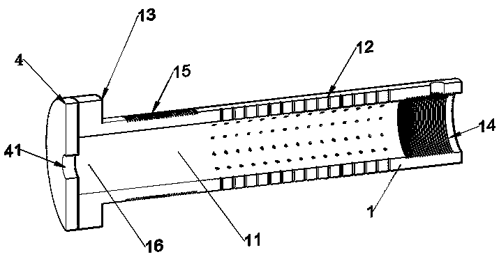
[0038] As a preferred embodiment, the sealing cover plate is a circular cover plate with a diameter equal to that of the flange 13 . The sealing cover plate is set to protect the gas leakage on the left side.

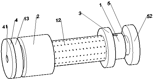
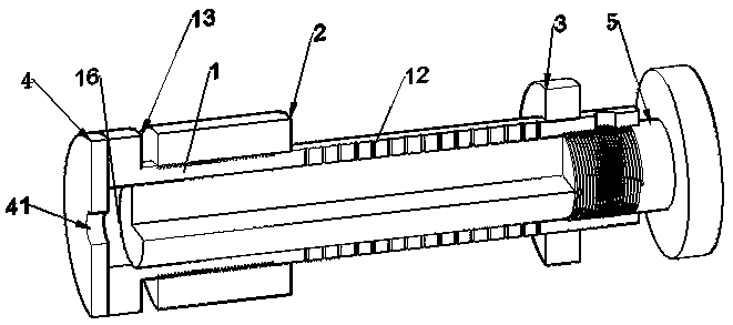
[0039] The air-blowing limit gauge of this embodiment enters the inside of the limit gauge by introducing gas, and sprays the gas onto the upper surface of the limit gauge through the air outlet, that is, the lower surface of the conveying material. To achieve the purpose of reducing the friction between the coil and the limit gauge. At the same time, the blown air can reduce the dust and ink on the limit gauge and improve the production quality. The inner core 5 of the limit gauge is installed on the material assembly line transmission equipment. When the outer gauge needs to be adjusted, the outer limit ring 2 is rotated, and when the inner gauge needs to be adjusted, the limit flange 13 on the shaft 1 is rotated. Therefore, when in use, since the inner core 5 of th...


PUM


Abstract

The invention discloses an air blowing type limiting gauge. The air blowing type limiting gauge comprises a shaft, an outer limiting ring and an inner limiting ring, wherein the outer limiting ring and the inner limiting ring respectively sleeve two ends of the shaft, a plurality of air outlet holes communicating with a hollow portion in the shaft are uniformly formed in the periphery, between theinner limiting ring and the inner limiting ring, of the shaft, and the shaft is provided with an air inlet for allowing gas to enter the hollow portion. The air blowing type limiting gauge outputs the gas through the air outlet holes in the periphery of the shaft, the gas fills between the periphery of the shaft and the lower surface of the material, and the gas is blown into the lower surface ofa material, so that the contact between the material and the peripheral surface of the shaft is reduced, the friction is reduced, the surface abrasion of the material is reduced, impurities such as dust or ink on the limiting gauge are reduced, the dustproof function is achieved, the production quality of the coiled material is improved, the abrasion of the limiting gauge is reduced, and the service life of the limiting gauge is prolonged.

Description

technical field [0001] The invention belongs to the technical field of production and manufacturing auxiliary tools, and in particular relates to an air-blowing limit gauge, which is mainly used in printing, semiconductor, metal processing and other flexible coil transportation fields to limit the position of flexible coils. Background technique [0002] Flexible materials, in the actual handling and transportation process, are mostly set in rolls, so the flexible coils need to be limited during transportation during processing. The limit gauge is specially used to limit the coil. The limit gauge includes shaft , the outer ring and the inner ring, the outer ring and the inner ring are respectively sleeved at both ends of the shaft, the shaft surface between the outer ring and the inner ring is used to transmit the material, and the material is bound by the cooperation of the inner ring and the outer ring to the inner ring, In the specific space between the two outer rings, i...

Claims


Application Information

Patent Timeline
Patent Type & Authority Applications(China)
IPC IPC(8): B65H23/26
CPCB65H23/26
Inventor 朱桂卿程建设叶亮
Owner HUBEI DANYAXIANG BIOLOGICAL TECH
Why Eureka
Try Eureka