Hydraulic transmission system and crane

A technology of hydraulic transmission and pressure cylinder, applied in cranes, fluid pressure actuating devices, mechanical equipment, etc., can solve problems such as reducing fretting performance and increasing production costs

Active Publication Date: 2021-04-23
ZOOMLION HEAVY IND CO LTD
View PDF14 Cites 0 Cited by
  • Summary
  • Abstract
  • Description
  • Claims
  • Application Information

AI Technical Summary

Problems solved by technology

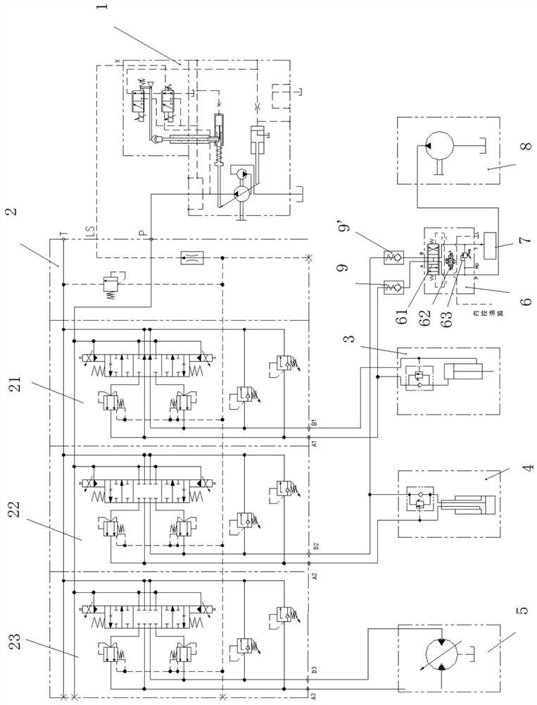
[0003] The purpose of the present invention is to overcome the problems existing in the prior art that the main valve adopts multi-piece large-flow electro-hydraulic proportional valves to increase the no-load and light-load luffing speed and the telescoping speed of the boom, which not only increases the production cost but also reduces the In order to solve the problem of its micro-movement performance, a hydraulic transmission system is provided, which can not only ensure that the crane using this hydraulic transmission system has good micro-motion performance at low speed with heavy load and low speed, but also can operate at light load and low speed. It has high luffing speed and boom telescopic speed when it is empty, and saves cost at the same time

Method used


Image

  • Hydraulic transmission system and crane
  • Hydraulic transmission system and crane
  • Hydraulic transmission system and crane

Examples


Embodiment Construction

[0022] Specific embodiments of the present invention will be described in detail below in conjunction with the accompanying drawings. In the present invention, it should be understood that the orientation or positional relationship indicated by the terms "deviating from", "facing", "upper", "lower", "front", "backward", "left", "right" etc. The orientation or positional relationship actually used is corresponding; "inner and outer" refer to the inner and outer relative to the outline of each component itself; it is only for the convenience of describing the present invention and simplifying the description, not to indicate that the referred device or element must be Having a particular orientation, being constructed and operating in a particular orientation, and therefore not to be construed as limiting the invention.

[0023] In the present invention, "micro-movement performance" refers to the ability to fine-tune the lifting mechanism or luffing mechanism in order to make th...


PUM


Abstract

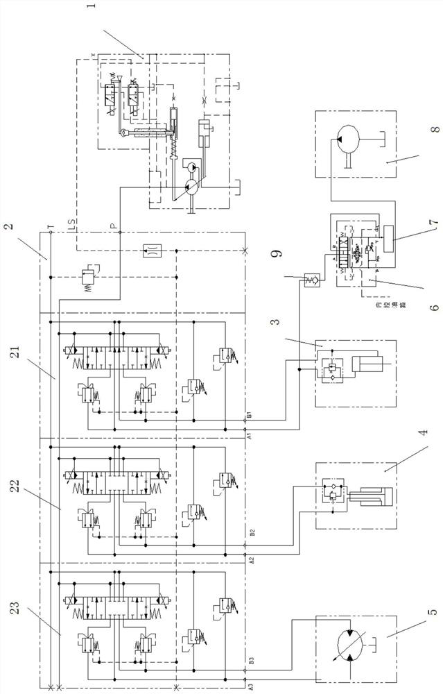
The invention relates to the technical field of engineering machinery, and discloses a hydraulic transmission system and a crane. The hydraulic transmission system includes a main control oil circuit and an auxiliary control oil circuit; the main control oil circuit includes a first power unit (1) and an execution unit and is connected between the first power unit (1) and the execution unit The first control module (2) used to control the action of the execution unit; the hydraulic oil output from the auxiliary control oil circuit can merge with the hydraulic oil output from the first control module (2) to control the execution unit. The hydraulic transmission system can not only ensure that the equipment using the hydraulic transmission system has good micro-movement performance under heavy load, but also meet the high-speed requirements under light load and no load, and can save costs.

Description

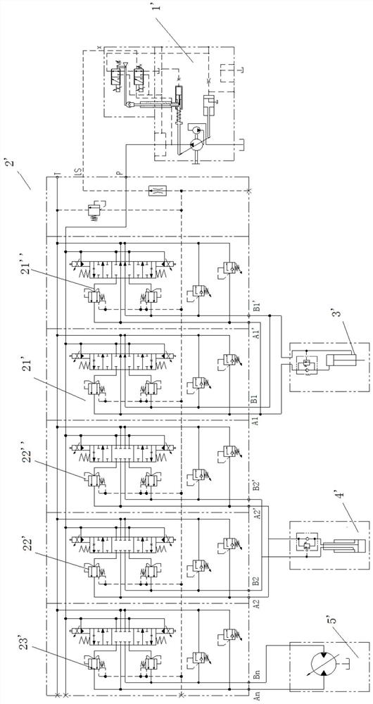
technical field [0001] The invention relates to the field of engineering machinery, in particular to a hydraulic transmission system and a crane. Background technique [0002] With the wide application of large-tonnage cranes in the market, users not only have higher requirements for luffing pressure and micro-movement, but also gradually increase the requirements for no-load and light-load luffing speed; The requirements are gradually increasing. Under normal circumstances, the power unit uses a variable pump 1'; the first control module 2' uses multiple large-flow electro-hydraulic proportional valves, of which one is used to control the luffing mechanism 3', and one is used to control the boom telescopic mechanism 4 ', one piece is used to control the hoisting mechanism 5', so that the requirements of general cranes can be met. In order to meet the customer's requirements for no-load, light-load luffing speed and boom telescoping speed, such as figure 1 In one embodime...

Claims


Application Information

Patent Timeline
Patent Type & Authority Patents(China)
IPC IPC(8): F15B11/042F15B11/17F15B13/06B66C23/693B66C13/20
CPCB66C13/20B66C23/705F15B11/0426F15B11/17F15B13/06
Inventor 李武胡廷江李英智沈昌武
Owner ZOOMLION HEAVY IND CO LTD
Why Eureka
Try Eureka