Hydraulic valve for forklift lifting

A hydraulic and valve technology, which is applied in the field of hydraulic valves for forklift lifting, can solve problems such as poor micro-movement, stuck hydraulic valve core, forklift can not be reset, etc., to achieve good micro-movement, stable control effect

Pending Publication Date: 2018-08-31
江苏海洲液压件制造有限公司
View PDF0 Cites 0 Cited by
  • Summary
  • Abstract
  • Description
  • Claims
  • Application Information

AI Technical Summary

Problems solved by technology

[0003] In order to overcome the problems existing in the prior art that the spool of the hydraulic valve will be stuck during the lifting process of the electric forklift, which will cause the forklift to fail to reset, the control is not stable, and the fretting performance is too poor. Lifted Hydraulic Valves

Method used


Image

  • Hydraulic valve for forklift lifting
  • Hydraulic valve for forklift lifting
  • Hydraulic valve for forklift lifting

Examples


Embodiment Construction

[0021] The specific embodiments of the present invention will be further described below in conjunction with the accompanying drawings. It should be noted here that the descriptions of these embodiments are used to help understand the present invention, but are not intended to limit the present invention. In addition, the technical features involved in the various embodiments of the present invention described below may be combined with each other as long as they do not constitute a conflict with each other.

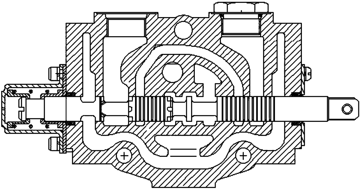
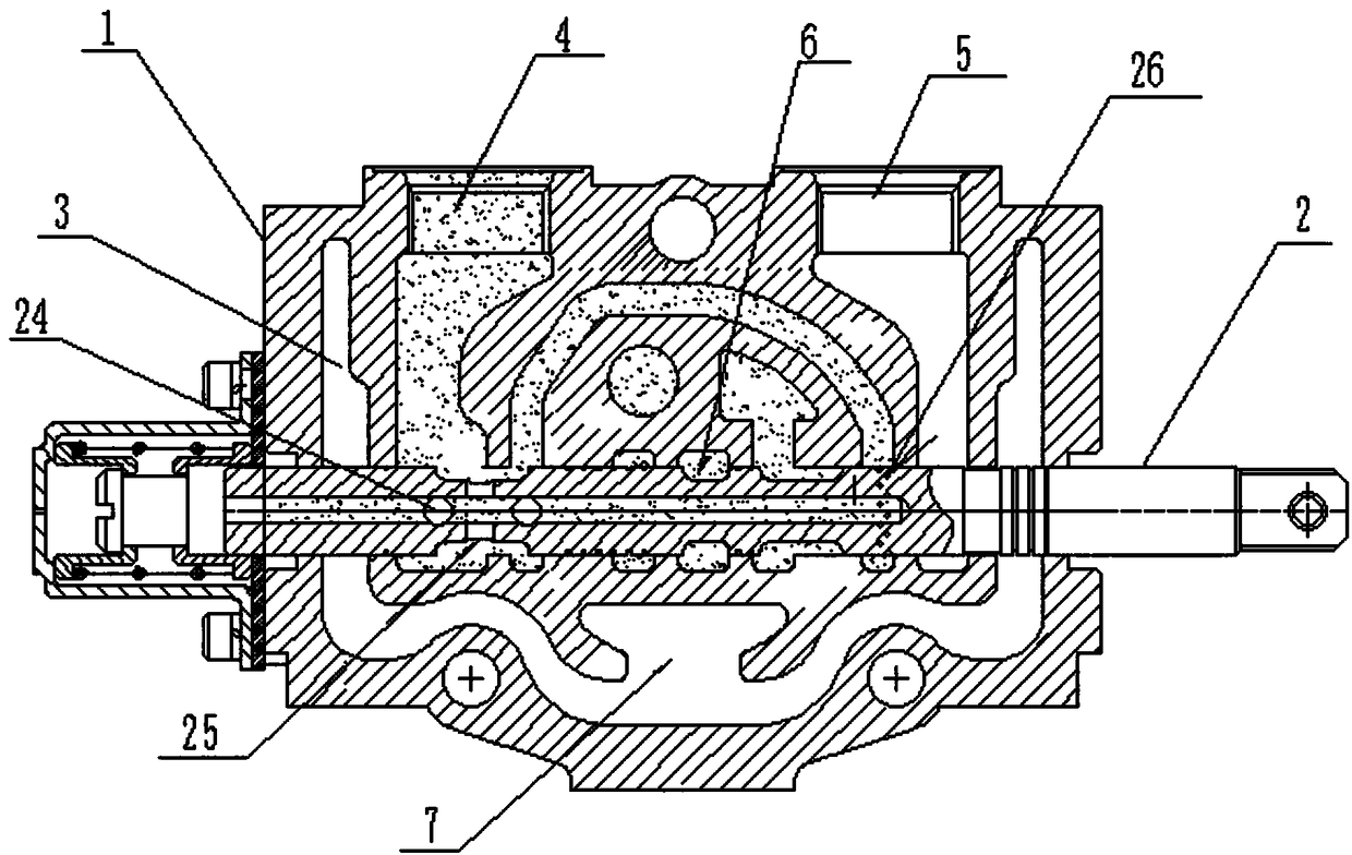
[0022] The invention provides a hydraulic valve for forklift lifting, such as image 3 As shown, including the valve body 1 and the valve core 2, the valve body 1 is provided with an oil channel 3 inside, the valve core 2 runs through the valve body 1, and is arranged in the middle of the valve body 1, and the two sides of the upper surface of the valve body 1 are respectively provided with working Port A4 and working port B5, the valve body 1 is provided with an oil in...


PUM


Abstract

The invention discloses a hydraulic valve for forklift lifting. The hydraulic valve for forklift lifting comprises a valve body and a valve element, wherein an oil path channel is formed in the valvebody; the valve element penetrates through the valve body and is arranged in the middle of the valve body; a working port A and a working port B are separately formed in the upper surface of the valvebody; an oil inlet cavity is formed in the valve body; an oil return cavity is formed in the lower end of the oil inlet cavity through the valve element; the valve element comprises a valve element a, a valve element b and a valve element c; two vertical through holes are vertically formed in the tail end of the valve element b, and the valve elements a, b and c are integrally formed. The hydraulic valve provided by the invention is steady in lifting operation and safe and reliable and has a good micro-motion property.

Description

technical field [0001] The invention relates to the technical field of hydraulic control systems, in particular to a hydraulic valve used for lifting a forklift. Background technique [0002] Electric forklifts refer to various wheeled vehicles for loading and unloading, stacking and short-distance transportation of palletized goods. Hydraulic energy is often used to lift goods, such as figure 1 Shown is a sectional view of a hydraulic valve in the prior art, and figure 2 It is a cross-sectional view of the spool in the valve, but the spool of the hydraulic valve will get stuck during the lifting process of the existing electric forklift, which will cause the forklift to fail to reset, the control is not stable, and the fretting performance is too poor. Contents of the invention [0003] In order to overcome the problems existing in the prior art that the spool of the hydraulic valve will be stuck during the lifting process of the electric forklift, which will cause the ...

Claims


Application Information

Patent Timeline
Patent Type & Authority Applications(China)
IPC IPC(8): F15B13/02B66F9/22
CPCF15B13/021B66F9/22
Inventor 吴建雄
Owner 江苏海洲液压件制造有限公司
Why Eureka
Try Eureka