
Variable pump hydraulic circuit and construction machinery

A hydraulic circuit and construction machinery technology, applied in the direction of mechanical equipment, fluid pressure actuators, servo motors, etc., can solve the problems of poor fretting, affecting fretting performance, and unstable flow, so as to avoid adverse effects, Good fretting performance, guaranteed effect of fretting performance

Active Publication Date: 2016-05-11
SANY AUTOMOBILE HOISTING MACHINERY
View PDF6 Cites 0 Cited by
  • Summary
  • Abstract
  • Description
  • Claims
  • Application Information

AI Technical Summary

Problems solved by technology

[0003] Compared with the valve-controlled hydraulic system, the pump-controlled hydraulic system has the advantages of high efficiency, but the dynamic response speed and control accuracy need to be improved. One of the reasons is that the variable displacement pump has the disadvantage of being under the condition of small displacement due to its own structural characteristics. The output flow instability characteristic (referred to as the small displacement instability characteristic), which often affects the micro-motion performance of the actuator under the small displacement condition of the variable pump; specifically, it is assumed that the small displacement flow instability range of the variable pump is Q≤Q 0 (L / min), when the displacement of the variable pump is less than or equal to Q 0 When the output flow is unstable, if the flow in this range is directly used to drive the actuator for inching, the inching performance is not good, even if the unstable flow source is used to drive the actuator to move, it is difficult to obtain stable inching performance

Method used


Image

  • Variable pump hydraulic circuit and construction machinery
  • Variable pump hydraulic circuit and construction machinery
  • Variable pump hydraulic circuit and construction machinery

Examples


Embodiment Construction

[0030] It should be pointed out that the description and sequence of specific structures in this section are only descriptions of specific embodiments, and should not be considered as limiting the protection scope of the present invention. In addition, the embodiments in this section and the features in the embodiments can be combined with each other under the condition of no conflict.

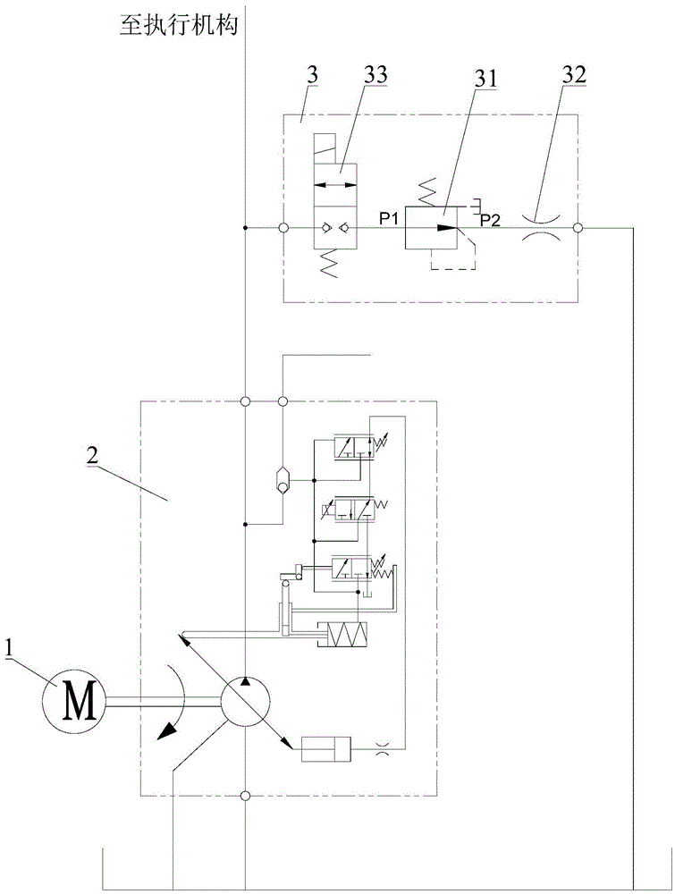
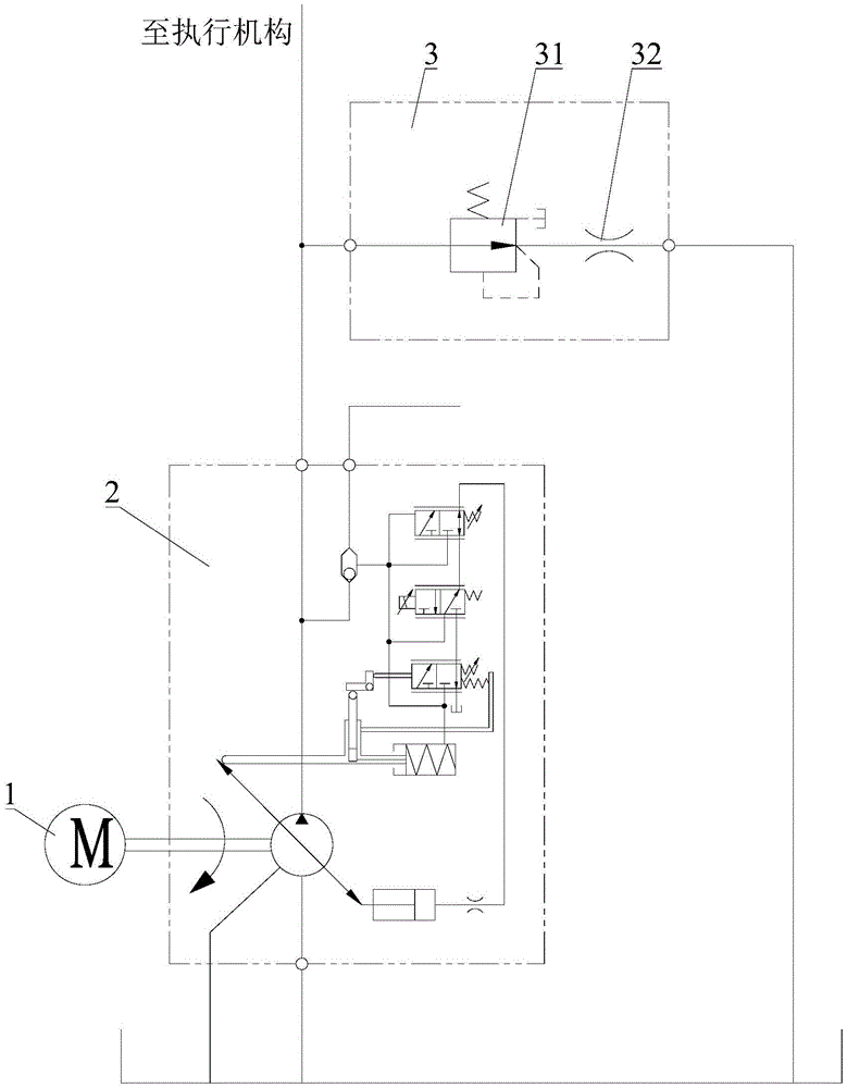
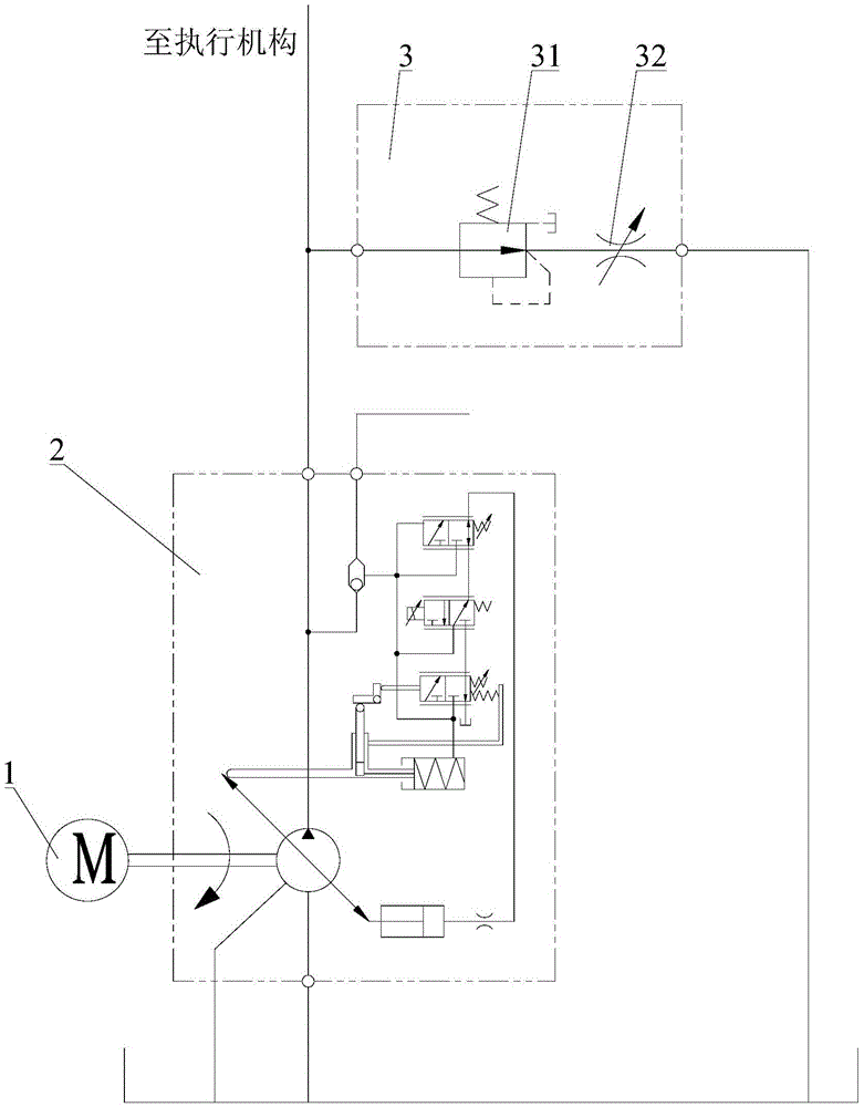
[0031] Please refer to figure 1 , figure 2 with image 3 , the present invention is described in detail below in conjunction with accompanying drawing. It should be noted that, in order to facilitate public understanding, figure 1 , figure 2 with image 3 The power device 1 is shown in both, but the hydraulic circuit of the variable pump in each embodiment of the present invention may not include the power device 1 .

[0032] Such as figure 1 As shown, the hydraulic circuit of the variable pump in the first embodiment of the present invention includes an oil tank (shown in the figure ...


PUM


Abstract

The invention discloses a variable pump hydraulic circuit and engineering machinery. The variable pump hydraulic circuit includes an oil tank, a variable pump, a constant pressure reducing valve and damping. The oil inlet of the variable displacement pump is connected to the oil tank, the oil outlet is connected to the oil inlet of the constant pressure reducing valve, and the oil outlet of the constant pressure reducing valve is connected to the oil inlet of the damper , the oil outlet end of the damping is connected to the oil tank. When the variable pump hydraulic circuit of the present invention is used to supply pressure oil to the actuator, since the constant pressure relief valve and damping cooperation can provide a stable bypass throttling for the variable pump, the variable pump does not need to work in an unstable range of flow and can be used for the actuator. The micro-movement of the mechanism provides a stable flow rate, which can effectively ensure the stability of the micro-motion performance of the actuator, and avoid the adverse effects of the unstable flow characteristics on the micro-motion performance of the actuator under the small displacement working condition of the variable displacement pump.

Description

technical field [0001] The invention relates to the technical field of variable pump hydraulic systems, in particular to a variable pump hydraulic circuit and engineering machinery. Background technique [0002] At present, valve-controlled hydraulic systems and pump-controlled hydraulic systems are commonly used in construction machinery. For example, small and medium tonnage cranes widely use valve-controlled hydraulic systems, while large-tonnage cranes use pump-controlled hydraulic systems. The valve-controlled hydraulic system is also called the throttling control hydraulic system. It is generally composed of a quantitative pump and a flow valve (overflow valve, throttle valve, etc.). During use, the size of the flow area of ​​the flow valve can be adjusted to change Flow into or out of an actuator, which in turn changes the speed of the actuator. The pump control hydraulic system is also called the volume control hydraulic system. It is generally composed of a variabl...

Claims


Application Information

Patent Timeline
Patent Type & Authority Patents(China)
IPC IPC(8): F15B13/02F15B11/02
Inventor 简桃凤禹阳华王坤
Owner SANY AUTOMOBILE HOISTING MACHINERY
Learn More