
Automatic light-chasing cloth airing device for spinning

A drying device and fabric technology, which is applied to dryers for drying solid materials, static materials, local stirring dryers, etc., can solve the problem of reducing the practicability and application scope of drying racks, increasing the difficulty of using drying racks, and increasing the drying time of fabrics. and other problems, to achieve the effect of increasing the scope of use, increasing the practicability, and improving the drying effect.

Active Publication Date: 2020-02-28
SUZHOU WANG YONGHENG SILK SCI & TECH CULTURE CO LTD
View PDF8 Cites 2 Cited by
  • Summary
  • Abstract
  • Description
  • Claims
  • Application Information

AI Technical Summary

Problems solved by technology

[0003] However, the existing drying devices are too simple in structure and crude in function in actual use, cannot adjust the height of the drying rack, increase the difficulty of using the drying rack, and reduce the practicability and scope of application of the drying rack. The position is fixed during the drying process, and the angle of the drying rack cannot be adjusted according to the different angles of sunlight, thereby reducing the effective use of sunlight, resulting in the inability of the fabric to dry, increasing the drying time of the fabric, and reducing the quality of the fabric at the same time. Textile Work Efficiency

Method used


Image

  • Automatic light-chasing cloth airing device for spinning
  • Automatic light-chasing cloth airing device for spinning
  • Automatic light-chasing cloth airing device for spinning

Examples


Embodiment Construction

[0031] The following will clearly and completely describe the technical solutions in the embodiments of the present invention with reference to the accompanying drawings in the embodiments of the present invention. Obviously, the described embodiments are only some, not all, embodiments of the present invention. Based on the embodiments of the present invention, all other embodiments obtained by persons of ordinary skill in the art without making creative efforts belong to the protection scope of the present invention.

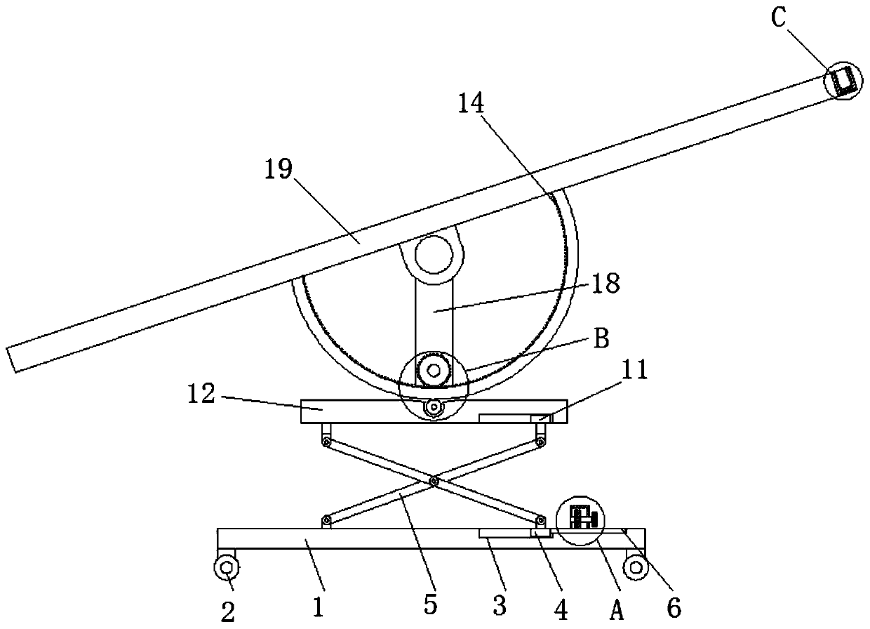
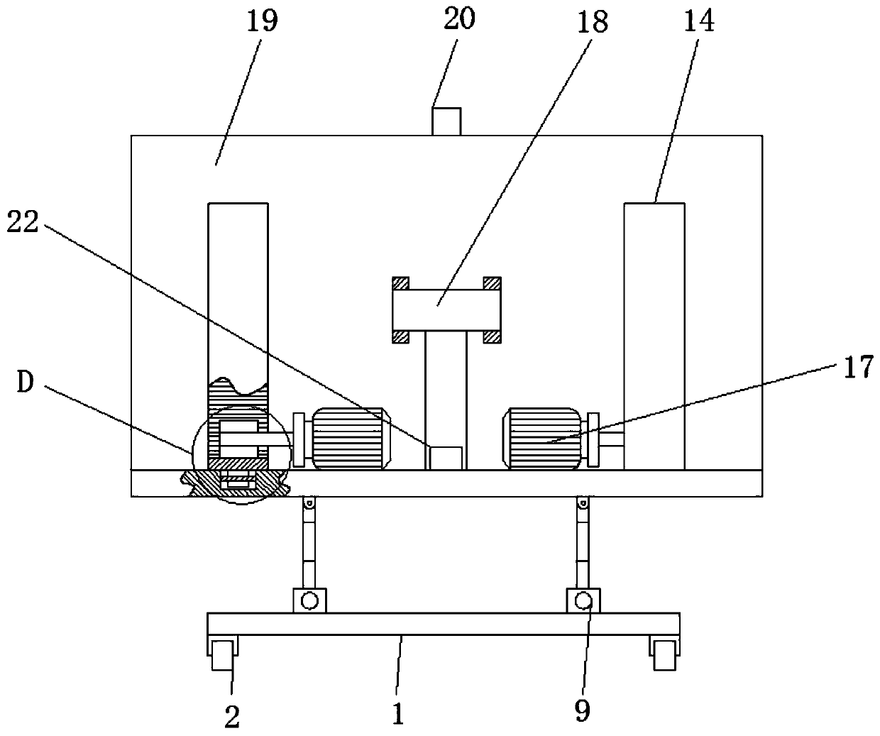
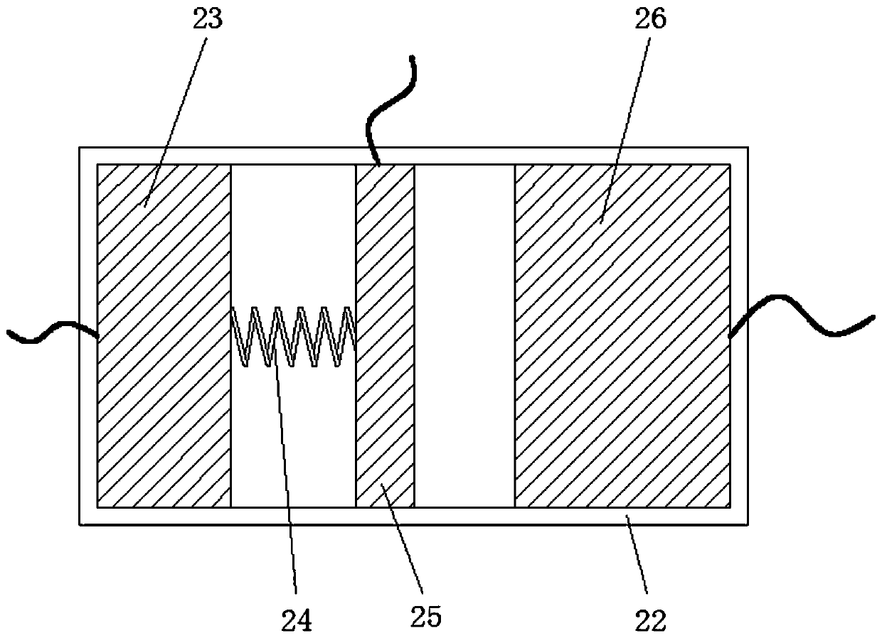
[0032] see Figure 1-10 , an automatic light-tracking fabric drying device for textiles, comprising a base 1, a universal wheel 2, a chute 3, a first slider 4, a lifting rod 5, a helical gear rod 6, a helical gear 7, an adjustment shaft 8, and a shell Body 9, knob 10, second slide block 11, mounting plate 12, support guide wheel 13, half gear ring 14, adjustment gear 15, rotating shaft 16, motor 17, support rod 18, drying rack 19, light transmittance device 20...


PUM


Abstract

The invention relates to the technical field of spinning, and discloses an automatic light-chasing cloth airing device for spinning. The automatic light-chasing cloth airing device comprises a base. Universal wheels are fixedly connected with the four corners of the bottom of the base. Slide grooves are formed in the top of the base. A first slider is slidingly connected into each slide groove. Alifting rod is hinged and connected to the top of each first slider. A helical tooth rod is fixedly connected with the outer portion of each first slider. The top of each helical tooth rod is meshed and connected with a bevel gear. An adjusting shaft is fixedly connected into each bevel gear. A shell is movably connected with the outer portion of each adjusting shaft. A rotary knob is fixedly connected with the outer portion of each adjusting shaft. A second slider is hinged and connected to the top of each lifting rod. An installing plate is slidingly connected with the outer portions of thesecond sliders. By means of the universal wheels, the position of the airing device can be conveniently and effectively adjusted at any time, the airing device is flexible to move and easy to operate,and the flexibility of the airing device is increased.

Description

technical field [0001] The invention relates to the technical field of textiles, in particular to an automatic light-tracking cloth drying device for textiles. Background technique [0002] The original meaning of textile is taken from the general term of spinning and weaving, but with the continuous development and improvement of the textile knowledge system and subject system, especially after the emergence of non-woven textile materials and three-dimensional composite weaving technologies, the current textile is not only a traditional Hand spinning and weaving also include non-woven fabric technology, modern three-dimensional weaving technology, modern electrostatic nano-netting technology and other clothing, industrial and decorative textiles. In general, after the textile fabric is processed, All need to use corresponding drying device to carry out drying operation to textile cloth. [0003] However, the existing drying devices are too simple in structure and crude in ...

Claims


Application Information

Patent Timeline
IPC IPC(8): F26B9/10F26B25/00F26B25/02F26B25/18
CPCF26B9/10F26B25/00F26B25/02F26B25/185
Inventor 沈琦伟
Owner SUZHOU WANG YONGHENG SILK SCI & TECH CULTURE CO LTD
Learn More