Placing device for computer CPU

A computer and body technology, applied in the field of computer CPU placement devices, can solve the problems of high production cost, reduced device practicability, lack of flexibility of the device, etc., to reduce maintenance and labor costs, reduce the probability of breaking, and increase the fixing effect. Effect

Inactive Publication Date: 2020-02-28
HUNAN UNIV OF SCI & ENG
View PDF3 Cites 2 Cited by
  • Summary
  • Abstract
  • Description
  • Claims
  • Application Information

AI Technical Summary

Problems solved by technology

[0004] One, when the existing device is fixing and protecting the computer CPU, due to the lack of elasticity of the existing device, when the existing device is fixing the computer CPU, the surface of the existing device and the computer CPU cannot be tightly attached together, which reduces the pressure of the device. The practicability of this device makes the fixing effect of fixing the computer CPU poor, reducing the practical effect of the device, so that the computer CPU is inside the device, and the vibration of the computer may cause the device to appear in the problem of collision inside the existing device Reduces the safety of the device and is not conducive to the practicability of the device
[0005] Two, when the existing device is in use, because the existing device cannot be closely attached to the outer surface of the computer CPU, the practicability of the device is poor, and the safety of the device is reduced, so that the device can be used for fixing the computer. CPU, the security of the computer CPU is low, which greatly increases the probability of damage to the computer CPU, increases the labor of the operator to replace and repair the computer CPU, and even causes a serious collision of the computer CPU inside the computer to cause the entire computer to be damaged. The scrapping of the CPU greatly increases the cost of replacing the computer CPU in the later stage of the device, which is not conducive to the economic benefits of the device and reduces the practical effect of the device
[0006] Three, when the existing device is in use, due to the complex structure of the device, it is difficult to disassemble when it is clamped. When the operator needs to repair and replace the computer CPU, the operator's work difficulty increases greatly, which makes the operator's work efficiency not high and reduces The flexibility of the device, due to the complex structure of the device, makes the production cost of the device higher, reduces the comprehensiveness of the device, is not conducive to the economic benefit of the device, and reduces the practical effect of the device

Method used


Image

  • Placing device for computer CPU
  • Placing device for computer CPU
  • Placing device for computer CPU

Examples


Embodiment approach

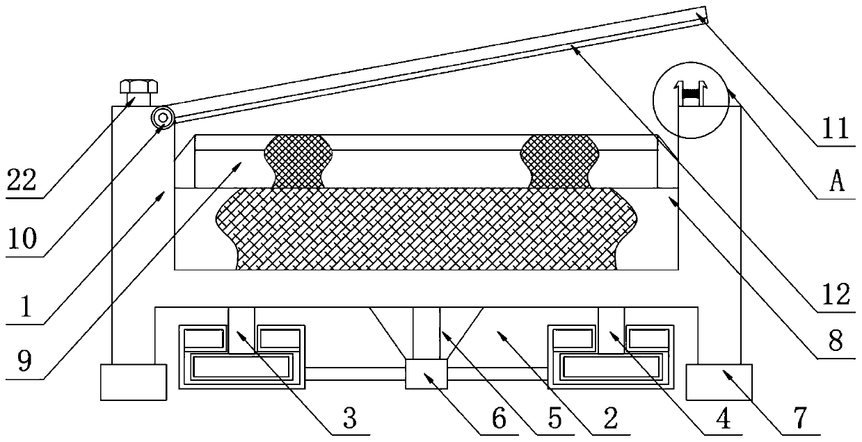
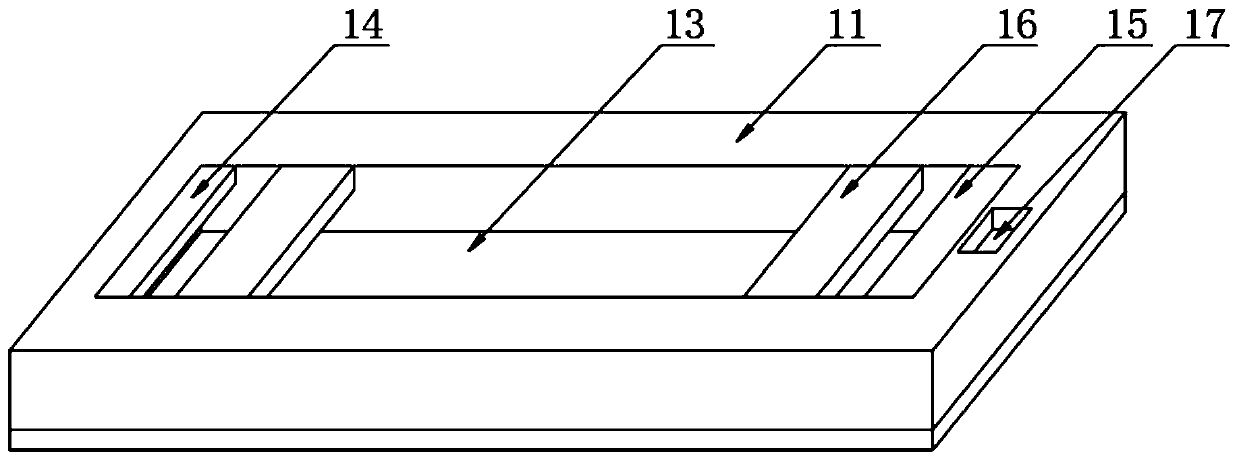
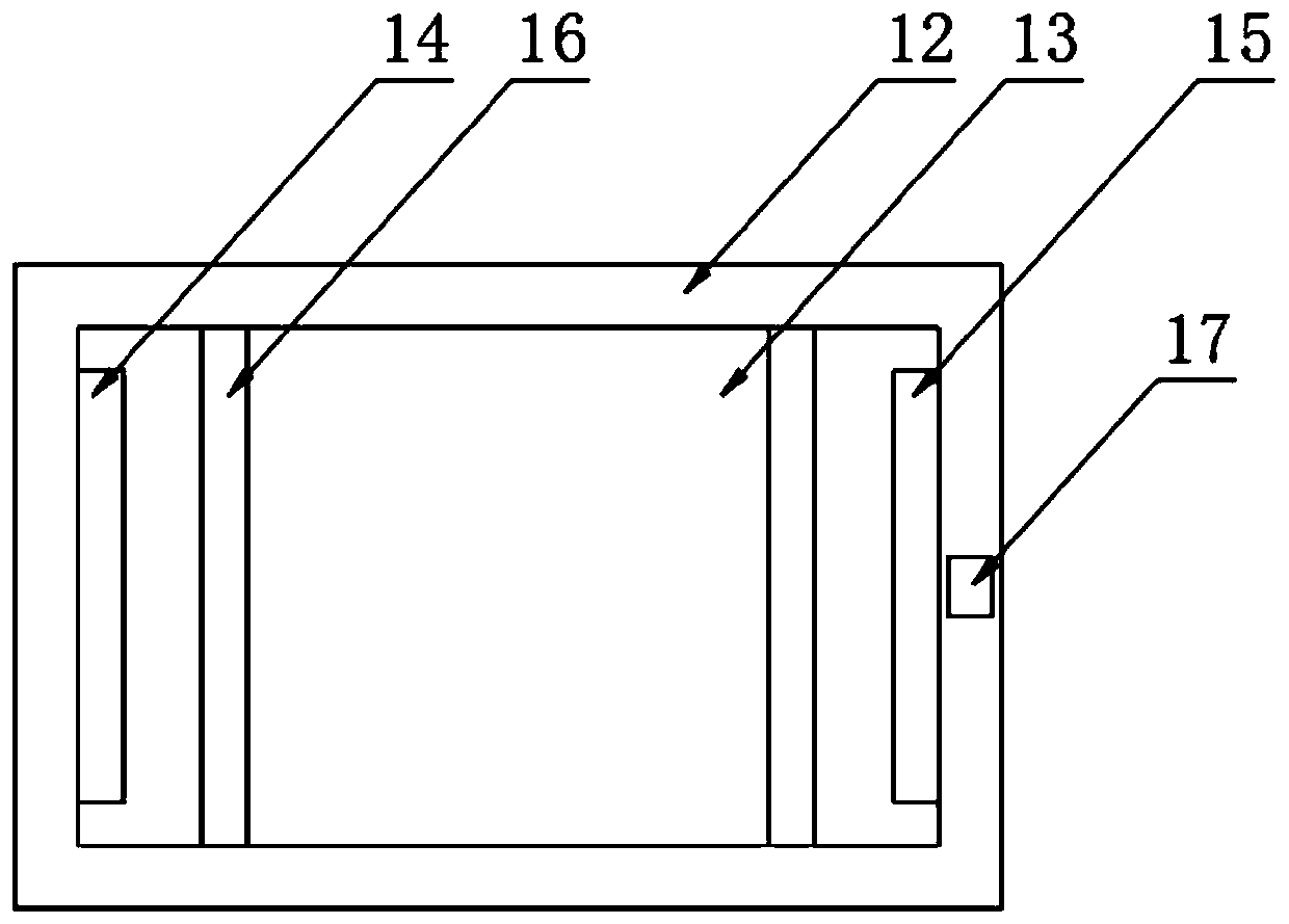
[0032] The specific implementation method is: the thickness value of the rubber pad 12 is utilized, so that when the device is fixing the computer CPU, the rubber pad 12 makes the card board 11 and the computer CPU closely fit together, increasing the card board 11 and the computer CPU. The stability between them greatly increases the practicability of the device and improves the economic benefits of the device.

[0033] Specific reference attached Figure 4 The active axis 10 includes an inner ring 101, the outer surface of the inner ring 101 is frictionally connected with a steel ball 102, the outer surface of the steel ball 102 is frictionally connected with an outer ring 103, the surfaces of the inner ring 101, the steel ball 102 and the outer ring 103 are smooth, and the steel ball 102 The quantity is several, and several steel balls 102 are located at the outer surface of the gap between the inner ring 101 and the outer ring 103 .

specific Embodiment approach

[0034] The specific implementation method is: the smooth surface of the inner ring 101, the steel ball 102 and the outer ring 103 is utilized, so that the resistance when the inner ring 101, the steel ball 102 and the outer ring 103 rub against each other is small, the sensitivity of the movable axis 10 is increased, and the Increase the practicability of the device, improve the practical effect of the device, increase the service life of the inner ring 101, the steel ball 102 and the outer ring 103, reduce the wear between them, improve the practicability of the device, and greatly increase the The economic benefit and practicality of the device.

[0035] Specific reference attached Figure 5 : the left side of the first clamping plate 18 and the second clamping plate 19 is integrally formed with a barb block, and the surface of the barb block is smooth, and the sum height value of the first clamping plate 18 and the second clamping plate 19 is slightly higher than that of th...


PUM


Abstract

The invention discloses a placement device for a computer CPU, in particular relates to the field of computer devices. The device comprises a device body, a straight groove is formed in the bottom endof the device body; a first base is fixedly mounted on the left side of the straight groove; a second base is fixedly connected to the right end of the straight groove, a connecting block is fixedlyconnected to the center of the bottom end of the straight groove, a supporting frame is fixedly installed on the bottom surface of the connecting block, a cushion block is bonded to the bottom end ofthe device body, a sponge plate is fixedly installed in the device body, and a fixing table is bonded to the top surface of the sponge plate. According to the invention, the rubber pad and the spongeplate are arranged; when the device is used for fixing the CPU of the computer; the clamping plate can be economically attached to the outer surface of the CPU of the computer; the situation that when a computer vibrates, the computer CPU collides with the clamping plate and moves is avoided, the fixing performance of the computer CPU is improved, and the problem that the computer CPU is scrappeddue to the fact that the computer CPU collides with the clamping plate seriously is avoided.

Description

technical field [0001] The invention relates to the technical field of computer devices, more specifically, the invention is a placement device for a computer CPU. Background technique [0002] A computer processor is the functional unit that interprets and executes instructions, also known as the central processing unit or CPU, which is the central nervous system of a computer, in contrast to the devices surrounding the processor and memory called peripherals, such as keyboards, monitors, Disks, tape drives, etc. are peripherals. Each processor has a unique set of operating commands, which can be called the instruction set of the processor, such as storage, transfer, etc., are all operating commands. Computer designers like to refer to computers as machines. Therefore, the instruction set Sometimes it is also called machine instructions, and the binary language used to write these instructions is also called machine language. The central processing unit is the computing co...

Claims


Application Information

Patent Timeline
Patent Type & Authority Applications(China)
IPC IPC(8): G06F1/16G06F1/18
CPCG06F1/1658G06F1/183
Inventor 杨杰杨环俊徐晓尹向东陈佩梁溢文谭道军刘小兵
Owner HUNAN UNIV OF SCI & ENG
Why Eureka
Try Eureka