Non-contact transformer auxiliary automatic cooling system and method

An automatic cooling and non-contact technology, applied in the field of transformer cooling, can solve the problems of obvious cooling effect and insufficient auxiliary cooling measures of transformers, so as to ensure the safety of personnel and equipment, improve aesthetics, and avoid maintenance work.

Active Publication Date: 2020-12-15
MEISHAN POWER SUPPLY CO STATE GRID SICHUAN ELECTRIC POWER CO
View PDF9 Cites 0 Cited by
  • Summary
  • Abstract
  • Description
  • Claims
  • Application Information

AI Technical Summary

Problems solved by technology

[0003] The purpose of the present invention is to provide a non-contact transformer auxiliary automatic cooling system and method to solve the problem of insufficient transformer auxiliary cooling measures in the prior art, and to achieve the purpose of automatic cooling of the transformer and the cooling effect is obvious

Method used


Image

  • Non-contact transformer auxiliary automatic cooling system and method
  • Non-contact transformer auxiliary automatic cooling system and method

Examples


Embodiment 1

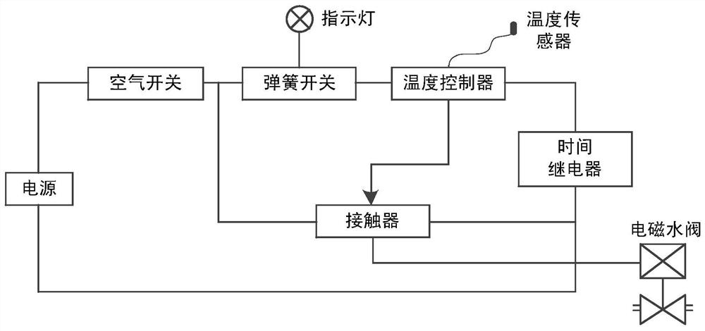
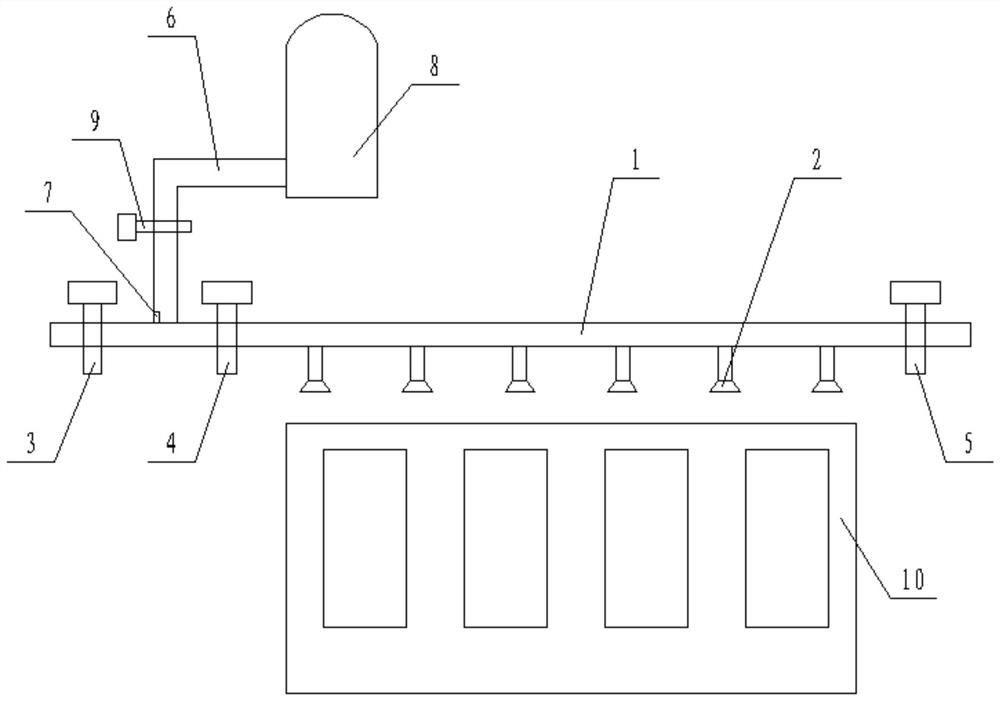
[0036] Such as figure 1 The shown non-contact transformer auxiliary automatic cooling system includes a temperature sensor used to collect the temperature of the transformer radiator, and the temperature sensor is connected to the temperature controller, time relay, intermediate relay, and electromagnetic water valve in sequence. The output end is connected to the spray pipe 1 through a hose, and several spray heads 2 are arranged on the spray pipe 1, and the spray heads 2 face the direction where the transformer is located.

[0037] Preferably, the intermediate relay is a contactor, and the contactor is used to control the electromagnetic water valve; the time relay is used to control the spraying time.

[0038] The device is characterized by small size, easy operation, arbitrarily expanded spraying system, and adaptability to transformers of various voltage levels.

Embodiment 2

[0040] Such as figure 1 and figure 2 As shown, on the basis of Embodiment 1, the spray pipe 1 is provided with a first shut-off valve 3, a second shut-off valve 4, and a third shut-off valve 5 in sequence along the direction from upstream to downstream. The first shut-off valve 3. The gas filling pipeline 6 is connected between the second shut-off valve 4, and the gas filling pipeline 6 communicates with the high-pressure gas source 8; the nozzle 2 is located between the second shut-off valve 4 and the third shut-off valve 5, and all nozzles are synchronized On and off. The gas filling pipeline 6 is located directly above the spray pipe 1 , and the axis of the gas filling pipeline 6 is perpendicular to the axis of the spray pipe 1 . A pressure sensor 7 is arranged on the inner wall of the gas filling pipeline 6 , and the pressure sensor 7 is located at the bottom of the gas filling pipeline 6 . A fourth shut-off valve 9 is arranged on the gas filling pipeline 6 , and the f...


PUM


Abstract

The invention discloses an auxiliary automatic cooling system and method for a non-contact transformer. The auxiliary automatic cooling system comprises a temperature sensor used for collecting the temperature of a transformer radiator, the temperature sensor is sequentially connected with a temperature controller, a time relay, an intermediate relay and an electromagnetic water valve, the outputend of the electromagnetic water valve is connected to a spraying pipe through a hose, the spraying pipe is provided with a plurality of spraying nozzles, and the spraying nozzles face the direction where the transformer is located. The invention aims to provide an auxiliary automatic cooling system and method for the non-contact transformer to solve the problem of insufficient auxiliary cooling measures of the transformer in the prior art and realize the purposes of automatically cooling the transformer and being obvious in cooling effect.

Description

technical field [0001] The invention relates to the field of transformer cooling, in particular to a non-contact transformer auxiliary automatic cooling system and method. Background technique [0002] As the "heart" of the power grid, the transformer's safe and stable operation plays a decisive role in the safe and stable operation of the power grid. However, transformers often suffer from high operating temperature. Excessive operating temperature not only accelerates insulation aging, seriously reduces transformer life, but also reduces transformer load capacity, affects power supply safety, and even leads to unplanned outage of transformers, and even lifelong damage. Auxiliary cooling measures for the high operating temperature of the main transformer caused by high power supply load mainly include: first, pile up dry ice around the transformer to reduce the ambient temperature and accelerate the heat dissipation of the transformer. This method has obvious cooling effect...

Claims


Application Information

Patent Timeline
Patent Type & Authority Patents(China)
IPC IPC(8): H01F27/16H01F27/18
CPCH01F27/16H01F27/18
Inventor 张磊李原龙杨晓冬杨雄金祖洋黄楠棋王志刚
Owner MEISHAN POWER SUPPLY CO STATE GRID SICHUAN ELECTRIC POWER CO
Why Eureka
Try Eureka