Deployable grid supports folded rib antenna reflector

An antenna reflector and grid technology, which is applied to antennas, electrical components, etc., can solve the problems of low stability of the profile system, easy changes in the profile, and easy deformation, and achieves high deployment reliability and deployment accuracy. High, stiffness-enhancing effect

Active Publication Date: 2021-06-18
SHANGHAI AEROSPACE SYST ENG INST
View PDF5 Cites 0 Cited by
  • Summary
  • Abstract
  • Description
  • Claims
  • Application Information

AI Technical Summary

Problems solved by technology

[0005] 2. After the antenna diameter becomes larger, the difficulty of forming and adjusting the reflective surface of the double-layer cable net structure increases, and the workload increases geometrically;
[0006] 3. In the harsh space environment, the cable net material of the antenna reflection surface is prone to creep and relaxation, which makes the profile of the antenna reflection surface easy to change. The stability of the profile system is not high, and it does not have a high profile. Surface accuracy and surface retention ability;
[0007] 4. The reflector is a whole system formed by stretching ribs and flexible cable nets. The structure has low rigidity and is prone to deformation, which in turn affects the performance of the antenna reflector.

Method used


Image

  • Deployable grid supports folded rib antenna reflector
  • Deployable grid supports folded rib antenna reflector
  • Deployable grid supports folded rib antenna reflector

Examples


Embodiment Construction

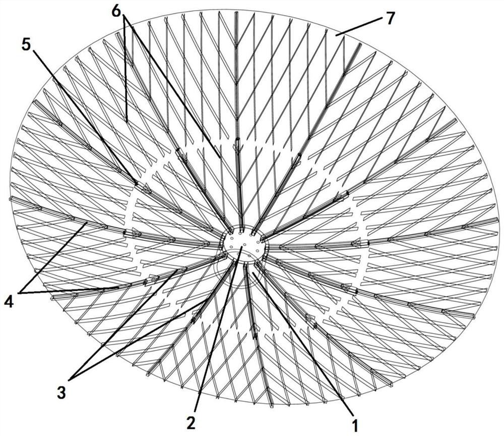
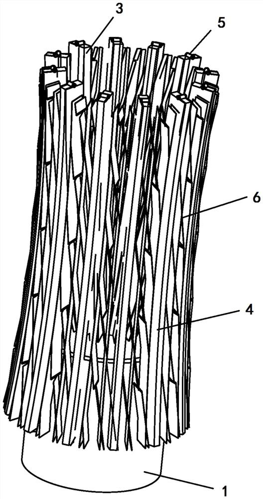
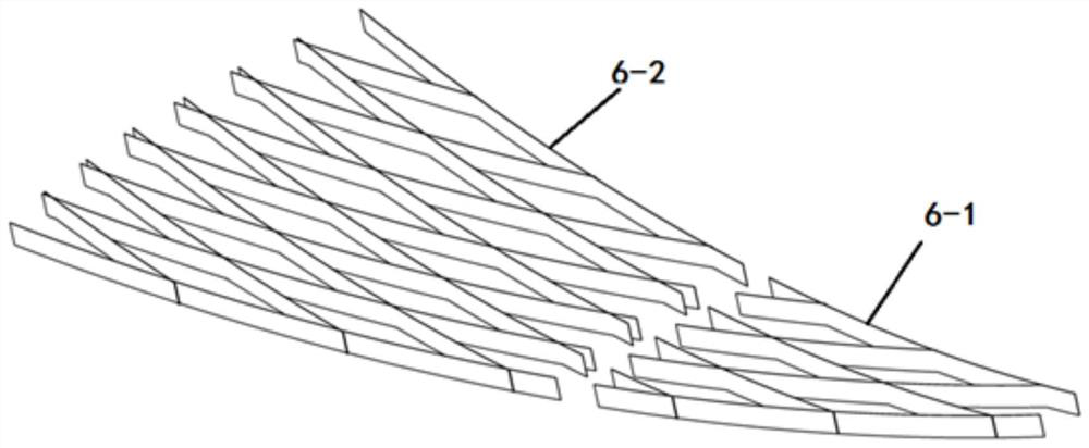
[0026] The present invention will be further described below in conjunction with specific embodiments and accompanying drawings. Marks in the figure: 1-antenna reflector base; 2-solid reflective surface; 3-inner folded rib; 4-outer folded rib; 5-intercostal rotation joint; 6-foldable support grid (6-1 : inner foldable support grid; 6-2: outer foldable support grid); 7-flexible reflective surface.

[0027] The deployable grid supporting folded rib antenna reflector of the present invention, see figure 1 , combine figure 2 , including an antenna reflector base 1 , a solid reflective surface 2 , an inner folded rib 3 , an outer folded rib 4 , an intercostal rotary joint 5 , a foldable support grid 6 and a flexible reflective surface 7 . One side of the base 1 of the antenna reflector is fixed on the antenna bracket to fix the antenna reflector, and the other end of the base of the reflector is connected to the solid reflection surface 2 . The expandable part includes an inner...


PUM


Abstract

The invention discloses a foldable rib-type antenna reflector supported by an expandable grid, comprising an antenna reflector base, a solid reflection surface, an inner layer of folding ribs, an outer layer of folding ribs, an inter-rib rotating joint, a foldable and expandable supporting grid and a flexible reflection The central area connected by the base is a high-precision solid reflective surface, and the edge of the base is connected to a radially unfolding grille supporting reflective surface. The expandable component includes a plurality of folded ribs on the inner and outer layers. The hinges and the rotating joints between the folding ribs realize the multi-level deployment of the antenna mechanism. The folding ribs are connected to the foldable support grid in the circumferential direction. The flexible reflection surface is laid on the folding ribs and the grid, and the expandable grid is woven It forms a foldable diamond shape, and the folding rib and grille support reflection surface end are processed according to the ideal curved surface or curve to eliminate the principle error. Large payload antenna reflector.

Description

technical field [0001] The invention relates to an antenna reflector, in particular to a folded rib antenna reflector supported by a deployable grid, which is applied to a large-scale high-precision rib antenna reflector in space. Background technique [0002] With the rapid development of satellite payload technology, spacecraft such as microwave remote sensing satellites, mobile communication satellites, data relay satellites, and electronic reconnaissance satellites have put forward requirements for larger and higher radio wave frequencies for spaceborne antennas. In order to obtain signals with low transmission power on the ground, improve the capacity of information transmission, and achieve high resolution of remote sensing, spaceborne antennas are developing in the direction of large aperture and high surface accuracy. Due to the limitation of carrying capacity, retractable and lightweight antennas are the development trend, and the radial rib deployable antenna is on...

Claims


Application Information

Patent Timeline
Patent Type & Authority Patents(China)
IPC IPC(8): H01Q15/16
CPCH01Q15/161
Inventor 王晓凯梁宝柱程庆清周鑫陈晓峰李向华施飞舟刘天明
Owner SHANGHAI AEROSPACE SYST ENG INST
Why Eureka
Try Eureka