Supercharge Your Innovation With Domain-Expert AI Agents!

Control method of dynamic reactive power compensation device for converter station

A technology of static reactive power compensation and compensation device, which is applied in reactive power compensation, AC network voltage adjustment, power transmission AC network, etc. The effect of voltage stabilization levels

Active Publication Date: 2020-02-28
ECONOMIC TECH RES INST STATE GRID QIANGHAI ELECTRIC POWER
View PDF5 Cites 0 Cited by
  • Summary
  • Abstract
  • Description
  • Claims
  • Application Information

AI Technical Summary

Problems solved by technology

If the dynamic reactive power compensation device used in the converter station still takes the AC bus voltage as the control target, in order to avoid the normal voltage fluctuation of the AC system, the output of the dynamic reactive power compensation device is within the normal range, and when the static reactive power compensation device is switched, the dynamic The reactive power output of the reactive power compensation device should not be too large, and the capacity of the dynamic reactive power compensation device cannot be completely used to suppress the voltage fluctuation of the switching of the static reactive power compensation device

Method used


Image

  • Control method of dynamic reactive power compensation device for converter station
  • Control method of dynamic reactive power compensation device for converter station
  • Control method of dynamic reactive power compensation device for converter station

Examples


Embodiment 1

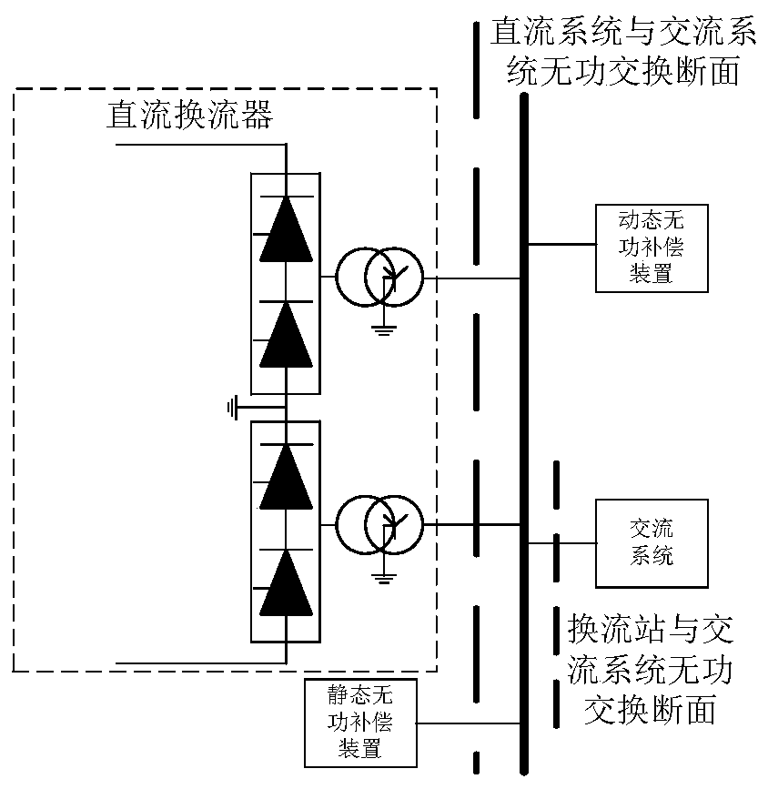
[0049] In this embodiment, the rated capacity of the HVDC transmission system is 8000MW. The short-circuit capacity of the converter station access system is 20000MVA. The converter station is equipped with 18 sets of static var compensation devices, each with a capacity of 300Mvar. The converter station is equipped with 2 sets of dynamic reactive power compensation devices, the specific type is static var compensator SVC, and the capacity of each set is 120Mvar, which can meet the requirements of reactive power grouping when one set is running. Since the capacity of each static var compensation device is 300Mvar, the maximum reactive power exchange between the converter station of the HVDC transmission system and the AC system is 225Mvar.

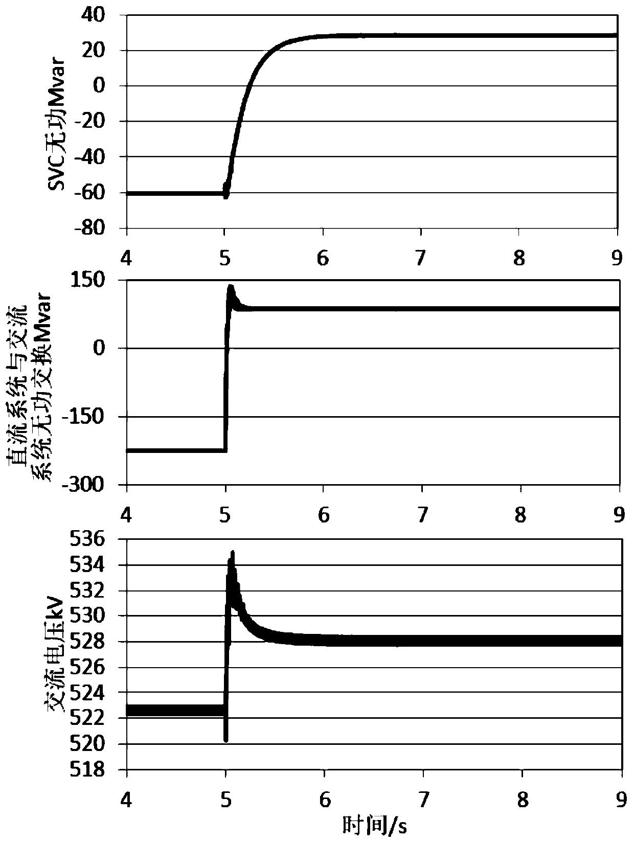
[0050] According to the formula (3), the proportional coefficient K is determined to be 0.266. image 3 It is a typical curve when the static var compensation device is put into use in this calculation example. Before putting in a set o...


PUM


Abstract

The invention discloses a control method of a dynamic reactive power compensation device for a converter station. The control method comprises the steps that 1) the dynamic reactive power compensationdevice collects reactive power exchange capacity of the converter station of a high-voltage direct-current power transmission system and an alternating-current system as control input; 2) first-orderinertia control is performed to enable reactive power output by the dynamic reactive power compensation device in a steady-state voltage operation range to be inversely proportional to reactive powerof a converter station injection system; and 3) amplitude limiting control is performed to enable the dynamic reactive power compensation device to absorb reactive power as much as possible when overvoltage occurs in the alternating current system and enable the dynamic reactive power compensation device to emit reactive power as much as possible when low voltage occurs in the alternating currentsystem. According to the invention, the capacity of the dynamic reactive power compensation device is mainly used for suppressing voltage fluctuation caused by switching of a static reactive power compensation device, so that the number of the static reactive power compensation device is reduced by using relatively small capacity of the dynamic reactive power compensation device, and meanwhile, the voltage support of the dynamic reactive power compensation device to the system is also realized in emergency.

Description

technical field [0001] The invention relates to the technical field of power system operation and control, in particular to a control method for a dynamic compensation device of a user converter station. Background technique [0002] The converter station of HVDC transmission system based on current source commutation usually consumes a large amount of reactive power, usually about 40%-60% of the transmitted active power. The static reactive power compensation device is mainly composed of capacitors and is cheap. It is the main device used for reactive power compensation in the converter station of the HVDC transmission system. In order to meet the reactive power compensation needs of the converter station of the HVDC power transmission system, it is necessary to configure multiple sets of static reactive power compensation devices. Reducing the number of groups of static var compensation devices can save power distribution devices such as circuit breakers and save land occ...

Claims


Application Information

Patent Timeline
IPC IPC(8): H02J3/16H02J3/36
CPCH02J3/16H02J3/36Y02E40/30Y02E60/60
Inventor 田旭温生毅张海宁李红霞刘飞张君宋涵彬王世斌车琰瑛
Owner ECONOMIC TECH RES INST STATE GRID QIANGHAI ELECTRIC POWER
Features
  • R&D
  • Intellectual Property
  • Life Sciences
  • Materials
  • Tech Scout
  • Unparalleled Data Quality
  • Higher Quality Content
  • 60% Fewer Hallucinations
Learn More